Our heavyweight helicopter equal in the world does not have
In Rostov started production of the most load-lifting rotary-wing car The Russian holding «Helicopt[...]

Everything about aircrafts and helicopters. News and events in aviation worldwide. Civil, transportation, military helicopters and airplanes.

Everything about aircrafts and helicopters. News and events in aviation worldwide. Civil, transportation, military helicopters and airplanes.

Everything about aircrafts and helicopters. News and events in aviation worldwide. Civil, transportation, military helicopters and airplanes.

Everything about aircrafts and helicopters. News and events in aviation worldwide. Civil, transportation, military helicopters and airplanes.


The tail rotor is a flapping rotor without cyclic pitch and is thus similar to the early autogiro rotors for which the blade element theory was originally developed. (Note: Even in tail rotors that have no hinges and are thus classified as rigid rotors, the aerodynamic and centrifugal forces generally predominate over the structural stiffness, and the rotor will flap by bending the blades almost as much as if it had actual mechanical hinges. The equations developed here can, therefore, be assumed to apply in the first approximation to these rotors.) Most tail rotors—and some main rotors—are designed with a mechanical coupling between flapping and feathering such that a change in flapping produces a change in feathering:
A0 = AP tan 53
where 83 is the slant angle of the flapping hinge as shown in Figure 3-45. The angle shown there is negative, which is the usual (but not the universal) application on tail rotors. The local blade pitch angle is:
T
0 = (0O + a0 tan 53) +0!—————- ax tan 53 cos |/ — bx tan 83 sin jf
R
The last two terms have the form of cyclic pitch and can be used in the basic rotor equations by treating them as such:
A, = a. tan53
leff. J
Van8>
Unlike the case of the main rotor, where the angle of attack of the tip path plane is known from equilibrium conditions, for a tail rotor the angle of attack of the shaft is known. It is generally zero unless the tail rotor shaft is deliberately tilted or the helicopter is flying with sideslip. For this reason, the tail rotor equations are written in terms of the inflow ratio, X.
where the subscript T denotes that all parameters refer to the tad rotor. Table 3.1 shows the trim conditions for the tail rotor of the example helicopter at 115 knots for 83 values of 0°, 30°, and —30°. It may be seen that the effect of the delta-three
 |
hinge on the trim conditions is small enough to be considered negligible for performance calculations.
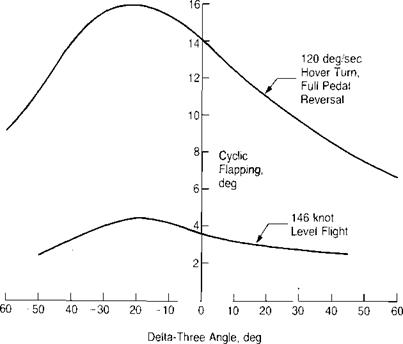
Although it has little effect on steady-state conditions, the delta-three angle is important in reducing flapping during maneuvers. Figure 3.47 from reference 3.30 shows that both positive and negative values are effective.
|
TABLE 3.1 Tail Rotor Trim Conditions
|
|
FIGURE 3.47 Effect of Delta-Three Angle on Rotor Flapping During Maneuvers |
Source: Huber & Frommlett, “Development of a Bearingless Helicopter Tail Rotor,” 6th European Rotorcraft Forum, 1980.