Our heavyweight helicopter equal in the world does not have
In Rostov started production of the most load-lifting rotary-wing car The Russian holding «Helicopt[...]

Everything about aircrafts and helicopters. News and events in aviation worldwide. Civil, transportation, military helicopters and airplanes.

Everything about aircrafts and helicopters. News and events in aviation worldwide. Civil, transportation, military helicopters and airplanes.

Everything about aircrafts and helicopters. News and events in aviation worldwide. Civil, transportation, military helicopters and airplanes.

Everything about aircrafts and helicopters. News and events in aviation worldwide. Civil, transportation, military helicopters and airplanes.


Perfectly elliptical wings are not easy either to lay out on the drawing board, or to build’ accurately. Many good compromise shapes are available and these can be made lighter, because of their simplicity, so the small aerodynamic losses may safely be ignored. Several popular examples are shown in Figure 6.3. Of these, (a) was commonly found on full-sized sailplanes during the 1920s and 1930s, and still appears on many models. If used, it might be slightly modified by employing a squared tip, as shown. The curved
|
|
|
|
|
|
|


trailing edge is not altogether easy to build. Ribs over this section of the wing cannot be made by the ‘sandwich’ method of construction. Each rib has to be plotted and cut individually. The form in Fig. 6.3b is very good from a structural point of view, giving ample root depth for spars, and can be safe If the tip chord is not reduced too far. The stall will occur first somewhere about half way out along the wing (Fig. 6. lc). This will usually cause a mild wing drop and for aerobatic models this may help to enter spins and flick rolls. The uncontrollable tip stall of the too-strongly tapered wing, however, is never desirable. Tip stalling can be avoided altogether by carefhl choice of aerofoil section, as will be discussed in Chapter 7.
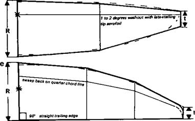
The planform (c) in Fig. 6.3 is good in all respects except that the root tends to be somewhat thin. It is easy to build and the departure from the ellipse is quite small. A convenient place for a dihedral joint is provided by the start of the tapered panel. Calculations by F. X. Wortmann suggest that if such a wing is built with three degrees of washout (i. e. reduction of incidence towards the tip), its performance is improved oveT a wide range of speeds. The washout should be progressive along the entire semi-span, rather than confined to the tapered panels only, as modellers usually do it
The planform in Fig. 6.3d is that currently preferred by most designers of full-sized sailplanes. The approximation to the ellipse is very close and the wing root is deeper than for the previous type. To build such a wing requires a little more work, but if ribs are cut by the sandwich method only one extra template is needed, for the semispan position, and it is possible to space the ribs more widely with lighter spars and covering over the outer panels, if desired, to save mass. Again, a convenient dihedral joint is provided, and on larger models the wing may be designed to part at the mid-span position for transport
It is argued by some aerodynamicists that a wing will produce a trailing vortex at every point where the trailing edge departs from a straight line. This is probably true where there is a marked change of dihedral, as on many model aircraft, or if there is a sharp break of taper. Following this argument some designers have adopted the planform shown in Figure 6.3e. The trailing edge of the wing is straight and is drawn at 90 degrees to the aircraft centre line. All the taper, still approximating the elliptical chord distribution, is on the leading edge. The result is a slightly swept back wing with respect to the quarter chord line so the aerodynamic centre of the whole wing is aft of the root quarter chord, which must be taken into account when positioning the centre of gravity.
Whether such a planform produces any detectable gain in vortex drag is hard to discover in practice.
|
Fig. 6.4 Planform to be avoided
|
6.5 BAD PLANFORMS
Some models have appeared with the planform shown in Figure 6.4. This is no doubt intended to reduce the interference drag where the wing root meets the fuselage, but the effect is wholly bad. Vortices are created which reduce the effective span and aspect ratio of the wing. The result is somewhat similar to opening a gap between wing and fuselage at the root, in effect making the monoplane wing into two separate surfaces. On some scale models of very early aeroplanes and gliders, this may be inescapable but it has drastic influence on performance.