Control
The physical control requirement in a helicopter is no more than the application of appropriate cyclic, collective and tail rotor pitch settings. Implicit in this is the need for some form of rotor speed governing. However, the physical control requirement is only a small part of the overall process that is inevitably more complex. In order to perform useful missions in safety, the pitch settings of the rotors must be such that at all times the machine has, for example, the desired attitude, airspeed, altitude and geographical location.
In order to control the flight, information must be gathered about the present conditions, and these must be compared with the desired conditions. Any discrepancies must result in changes to the physical controls that would tend to reduce discrepancies to zero or at least as near as makes no difference. This is, of course, classical negative feedback as was introduced in Chapter 2. The essential components of this process must be information gathering, or sensing, information transmission, decision-making, or information processing, all of which takes place with small amounts of power, followed by a power amplification stage that allows the control information actually to operate the controls.
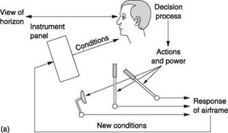
Figure 7.1(a) shows the case of a simple light helicopter. It will have instruments such as airspeed indicator, altimeter and compass whose output is purely visual. The pilot looks at the instruments and out of the canopy in order to establish the actual conditions, but has to perform all of the actions necessary to stabilize the machine and hold it on a desired course. The machine itself may actually be unstable, in that left to itself it would diverge from its original course, but the combination of the pilot and the machine can be a stable system. In other words the pilot is working out the difference between what is wanted and what is actually happening. As a result of a difference of this kind the pilot then has to operate one or more of the controls in a sense that reduces the difference. An unskilled pilot may overcontrol so that the machine oscillates about the desired course, whereas the experienced pilot will have learned the dynamics of the machine and applies just the right control inputs smoothly to bring the difference to zero.
In Figure 7.1(a) the pilot is part of a feedback loop and is not only computing the servo error, but is also mentally modelling the machine’s response to avoid instability. The pilot may also be providing all of the control power with his own muscles. This task must be performed for the duration of the flight, as the machine will diverge if attention lapses for more than a few seconds.
|
|
|
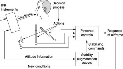
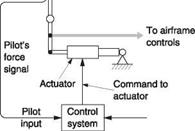
Fig. 7.1 (a) A minimal control loop in which the conditions are sensed from simple instruments and the view from the canopy. (b) Power assistance is provided for the controls, making possible the use of a stability augmentation device. |
Put this way, the pilot’s task sounds onerous, but it need not be so. In a simple light helicopter in good conditions this process is extremely enjoyable. However, many helicopters have to operate in poor conditions, and in addition to flying the machine the pilot may be required to perform other tasks associated with the mission. The goal of the designer may then be to make flight possible in all weathers, and/or to keep the pilot’s stress or workload down to an acceptable level for the expected mission.
The pilot’s assessment of the machine’s attitude is assisted by the provision of instruments such as an artificial horizon and a direction indicator. These will allow the pilot to maintain the machine’s attitude despite poor visibility and are essential if the machine is to be flown under instrument flight rules (IFR). The addition of power – assisted controls to Figure 7.1(a) will beneficially reduce the pilot’s physical workload on long flights. IFR instruments improve the quality of information presented, but the stability of the machine is still down to the continuous concentration of the pilot. Flying a simple helicopter on instruments is possible, but difficult. Two pilots might be required, one to fly, the other to handle navigation and communications.
Once powered controls are available, it is then a small step to make them accept signals from an automatic stabilizing system that can reduce the pilot’s mental workload. The stabilizing action of the pilot is augmented or even replaced by a signal processor programmed to respond to disturbances in the way a skilled pilot would. However, the signal processor has no eyes and needs information about the flight conditions in the form of input signals. Figure 7.1(b) shows that the aircraft instruments no longer just have a visual indication, but also output signals representing the current condition. It will also be seen in Figure 7.1(b) that the outputs of the signal processor can act upon the powered controls.
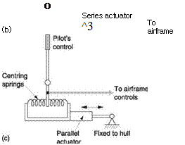
In such a machine there are two parallel control paths. Figure 7.2(a) shows that the control of the machine can be entirely by the pilot, entirely by the signal processor, or by a combination of both, with the possibility that the amount of contribution from each control path may also change throughout the flight. This must be the source of further complexity. It is fundamental to negative feedback that there can be only one overall feedback loop in a system. Two negative feedback loops around the same process will fight each other. For example, if the outputs of the pilot’s stick and the processor are simply added, by fitting what is known as a series actuator in the pushrod, the pilot’s controls cease to function. Figure 7.2(b) shows why. It is the goal of the processor to maintain the attitude of the machine. If the pilot applies, say, left cyclic, the machine will begin to bank left, but the processor will sense this as an error and apply right bank. The machine will continue to fly straight, with the processor precisely opposing everything the pilot does. If the pilot releases the stick, the series actuator may succeed in moving the stick instead of the controls.
In early systems using series actuators, engaging the autopilot must lock the stick in the neutral position to give the series actuator a mechanical reference against which to react. The pilot has to disengage the processor if he wants to resume control.
In the parallel actuator system shown in Figure 7.2(c) the actuator moves the mechanical reference of the stick centring springs. With the signal processor off, the actuator may perform the trim function. With the signal processor on, the pilot releases the stick and the actuator moves both stick and controls. This gives visual confirmation that the system is working, but more importantly the pilot can override just by moving the stick against the centring springs.
In modern systems there is a more convenient way. Figure 7.2(d) shows that the processor is permanently on, but the pilot’s stick is connected differently. If the stick is released, it has no effect and the processor controls the course. However, in order to override the processor, the pilot simply moves the stick as normal. This generates a false error that is fed into the processor. For example, if the pilot wishes to bank left, he moves the cyclic stick left, and this generates a signal that is added to the processor’s bank angle error to indicate falsely that there is a right bank condition. The processor acts to cancels that condition by performing a left bank.
Thus it will be seen that the way for the pilot to override a feedback system is not to attempt to oppose the output, which cannot work, but to modify the reference value or the parameter the system is trying to hold constant. In this way the system still stabilizes the override manoeuvre. For example, in the example of the left bank above, the system now acts to hold the bank angle constant. In the event of gusts disturbing the bank angle, the system would correct for them. In this way the combination of control system and real pilot is close to the ideal.
Figure 7.1(b) showed a simple stability augmentation system in which the goal is to reduce the naturally divergent behaviour of the helicopter as well as external disturbances from gusts using a parallel actuator. The reduced pilot workload may make single pilot instrument flying possible. Clearly the stability augmentation system must
|
|
|
|
|
|
|
|
|
|
|
|
|
|
 |
|
|
|
|
|
|
|
|
|
|

AUTOPILOT

![]()
Altimeter
encoder
ASI
encoder
Compass
encoder
Gyroscope
encoder
Dynamic turn sensor
Altitude
hold system
Airspeed
hold system
Heading
hold system
Stability
system
Fig. 7.3 With an autopilot, attitude, altitude, airspeed and heading can be controlled automatically, but the pilot must still select the course. With an autopilot coupled to a flight director, navigational inputs can control the autopilot so that a course can be held.
understand the dynamic response of the helicopter in order to avoid any overshooting or oscillation when correcting the attitude. The attitude of the machine is still controlled by the pilot, but the stability of the machine is improved by using attitude signals from the artificial horizon.
In Figure 7.3 the process has been taken one stage further. Here the augmented stability achieved in Figure 7.1(b) makes it possible for the machine to be controlled automatically. Inputs to the signal processor from the altimeter, the airspeed indicator and from a compass allow the machine to hold a heading without any action from the pilot. This system is generally called an automatic pilot or just an autopilot.
The system of Figure 7.3 relieves the pilot of the need to fly the machine continuously, but can only hold a heading and would not compensate for a change in wind strength or direction. However, with further inputs from a navigation system or from a flight director the machine could hold a course determined by a GPS receiver, VOR beacon or an instrument landing system (ILS). In this case the flight director creates a further feedback loop. The actual course is computed by navigational equipment and compared with the desired course. Any error is then fed to the autopilot as a modified heading reference.
In early helicopters, the provision of stability augmentation and autopilot systems was frequently optional, whereas in modern machines such systems are often designed in from the outset. One modern trend is away from instruments with a direct visual readout. Instead instruments may be used which have only an electrical output and are best called sensors or transducers. These outputs are supplied not only to the autopilot, but also to a display processor that produces a virtual instrument panel on a computer graphics-type display. This is known colloquially as ‘glass cockpit’ technology. One advantage is that the instruments themselves can be located anywhere convenient and do not have to be in the instrument panel.
In helicopters, the stability augmentation and autopilot capabilities may be extended into the hover. In this case altitude and airspeed information from atmospheric pressure is not good enough and instead RADAR will be used to measure height and ground – speed. In flying cranes and in search-and-rescue helicopters the ability to remain at a
fixed point in the hover despite external disturbances is extremely valuable. In advanced search-and-rescue helicopters the pilot simply presses a button as he flies directly over the victim and the helicopter will automatically perform a 360° turn and come to the hover at exactly the same place.
A helicopter with a suitable degree of automation does not need a pilot on board if the commands he would have given the autopilot can be transmitted by radio. This makes possible a range of devices from the simple radio-controlled helicopter, which must remain within the pilot’s view, to the autonomous drone that can undertake an entire mission without human intervention.
The provision of various control, stabilization or autopilot systems depends upon a number of fundamental technologies. These include the signalling of control positions from one place to another, power operation of controls, attitude sensing, altitude and airspeed sensing, parameter signalling and feedback control. The subject of safety must also arise. What happens if any of these mechanisms go wrong? These concepts will be considered in this chapter.
There are four main categories of flight instrument into which virtually any device can
be placed. These will be contrasted prior to a detailed discussion of each one.
(a) Heading sensing devices to display information relating to the direction the helicopter is pointing in. The most important of these is the magnetic compass that displays the magnetic heading or direction with respect to the earth’s magnetic field. The direction indicator (DI) is a gyroscopic device arranged to display the same heading as the compass. It is less affected by manoeuvres than the compass and is easier to read. The rate of turn indicator, usually just called the turn indicator, is a gyroscopic device that displays the rate at which the heading is changing and the direction of the change.
(b) Height sensing indicators display the vertical distance between the helicopter and some reference. The altimeter is a pressure-sensing device whose display is calibrated in feet or metres. It is important to use the appropriate reference or the display will be misleading. The RADAR altimeter is an electronic device which times the reflections of radio waves emitted downwards from the helicopter and so displays the height above ground. The vertical speed indicator measures the rate of change of air pressure and displays rate of altitude change and direction, usually in hundreds of feet per minute. Height information is also available from GPS receivers.
(c) The airspeed indicator (ASI) is a device that measures the dynamic pressure of the air caused by forward motion of the helicopter. The scale is calibrated in knots or mph. It is also possible to measure ground velocity using Doppler RADAR and this will allow the helicopter’s track to be established. In this way the heading can be adjusted to cancel the effects of wind.
(d) Attitude-sensing instruments display the attitude of the helicopter in pitch and roll with respect to the earth’s gravitational field. These are commonly gyroscopic and include the artificial horizon, which displays pitch and roll on one instrument, and the simpler rate of turn display.
The above classification is of most use to the pilot since in flight one is more concerned
with the readings themselves than how the instruments work internally. As well as
classification by the quantity displayed, instruments can also be categorized by the internal operating principles, and this is more appropriate to a technical description. The internal operating principle can be magnetic, pressure, gyroscopic, optical or radio and these principles will be examined in turn.
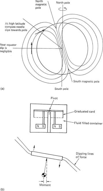
The simple compass is a small freely suspended magnet that attempts to align itself with the earth’s magnetic field. Figure 7.4(a) shows that the earth acts as if a large bar magnet were buried inside it. The north-seeking pole of the compass magnet (generally just called the north pole) is so called because it points to the north. As opposite poles attract, clearly the magnetic pole at the north end of the earth is actually a south pole. It is called the north magnetic pole because of where it is. Figure 7.4 also shows that as the lines of magnetic force return to the poles, they angle sharply into the ground. This is called magnetic dip and in the UK lines of force enter the ground at about 65° to the horizontal. A simple bar magnet suspended at its CM would adopt that angle of dip. Only the horizontal component of the earth’s field is useful for navigation so dip is clearly a nuisance. There is no dip at the equator since lines of force are parallel to the ground there. Near the magnetic poles compasses are useless.
The axis of the earth’s magnetic field is not aligned with the rotational axis, and so the magnetic poles are some distance from the true poles. The north magnetic pole has been wandering about in northern Canada in recent history. Maps are made with latitude/longitude grids that relate to the true poles, and so a line of longitude by definition points true north. As the magnetic pole is not at the true pole, a magnetic compass does not point to true north. Variation is measured in degrees and direction. For example, if the compass points 8° to the west of true north, the variation is 8°W
In order to use the magnetic heading for navigation, maps are drawn with additional lines which show the variation. A line joining all points having the same variation is called an isogonal line. On a map covering a large area, isogonals are drawn every 2°. There is one line joining places of zero variation called the agonal line and which currently passes through Sweden. On charts covering a small area in great detail the variation is shown once and can be considered to be the same over the whole chart.
Direction is expressed in degrees clockwise from North or by the cardinal points North, South, East and West and can be true (T) or magnetic (M). The degree symbol is often omitted and heading will simply be a three-digit number followed by the magnetic/true descriptor, e. g. 295M, 310T.
Runways are numbered according to their magnetic direction but rounded to twodigit accuracy. The runway name is painted at the landing end. Thus a runway running east-west would have 09 painted at the western end since this would be visible to an aircraft flying on a course of 90°. The number 27 would be painted at the opposite end where it would be seen by an aircraft flying on a course of 270°.
A simple bar magnet will also oscillate about true north if disturbed because the earth’s field acts like a weak spring and the magnet has rotational inertia. The balance wheel of a watch oscillates in the same way. In order to damp oscillations, aircraft compasses incorporate a liquid. Figure 7.4(b) shows the construction of a typical aircraft compass. The magnet is actually a number of magnets, typically four, embedded in a disc made of some non-magnetic material such as plastic. The outside of the disc is engraved with the magnetic heading which will be read off against a mark on the case
|
|
|
|
|
|
|
Deviation card for |
|||||||
|
N |
30 |
60 |
E |
120 |
150 |
||
|
Steer |
|||||||
|
359 |
29 |
60 |
91 |
121 |
151 |
||
|
For |
|||||||
|
S |
210 |
240 |
W |
300 |
330 |
||
|
Steer |
|||||||
|
179 |
209 |
240 |
271 |
301 |
330 |
||
|
On JxJ |
Radios |
□ No |
|
(d) |
Fig. 7.4 (Continued) (c) Deviation is an error in a magnetic compass due to a nearby ferrous object. (d) A deviation card shows what compass errors exist.
called the lubber line. Since the compass is invariably mounted ahead of the pilot, the lubber line will be at the back of the unit, and so the engraving is rotated 180° with respect to the magnet. Thus if the helicopter and pilot and magnet are all facing due north, the part of the disc with ‘N’ on it will be facing the pilot.
Compass dip is minimized by pivoting the disc well above the CM. If the dip exerts a tilting couple, the CM moves from below the pivot to balance it. The disc remains within 2 or 3° of horizontal as the vertical component of the earth’s field is thus opposed. The disc rotates until the magnet is parallel to the horizontal component of the earth’s magnetic field. Oscillation is prevented by the viscosity of the liquid acting on the large periphery of the disc.
The contact pressure between the pivot and the disc is reduced by buoyancy of the liquid and this reduces friction. When visualizing how a compass works, it is important to remember that the compass disc tries to keep pointing the same way as the helicopter turns around it.
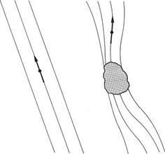
A magnetic compass is simple and reliable and needs no power, but it has a number of characteristics that need to be understood if it is to be used correctly. The compass can only align itself to the field it experiences. If something external to the compass disturbs the direction of that field, the compass cannot know and will point to a false north. The result is known as deviation and should not be confused with variation. This is shown in Figure 7.4(c). A helicopter contains a wealth of components that are necessarily magnetized such as the magnetos, the alternator, the electric fuel pump, the motors in the trim system and gyroscopic instruments and the moving coil drive units in the headsets.
Additionally many of the parts of a helicopter whilst not magnetic themselves are ferrous and can distort the earth’s field by their presence. Any steel tubing in the hull, the engine and gearbox and the crankshaft, con rods and gears are all ferrous. Aluminium, brass, glass fibre and plastics are non-ferrous and have no effect.
The sum of all of the effects of the helicopter’s structure on the compass determines the deviation. Before a helicopter can be released to service the deviation must be measured and displayed on a deviation card (Figure 7.4(d)) mounted next to the compass. The deviation card is completed at the end of a procedure called swinging the compass. The helicopter is taken away from buildings and aligned with each cardinal point in turn. The deviation due to the machine’s own magnetism can be detected by this process as at some points it will increase the compass reading and at other points it will reduce it. Sometimes the deviation can be reduced by the installation of ferrous compensators adjacent to the compass, but in any case the remaining deviation must be measured every 30° and recorded on the deviation card. This should be done with the engine running as a rotating permanent magnet has less effect than when it is stationary. Since radios can also generate magnetic fields, these must be tested for deviation effects.
It was stated above that the dip of the compass is overcome provided the disc stays horizontal. Unfortunately there are occasions in the normal flight of a helicopter when this is not the case and the compass dip is not overcome but acts to give an erroneous reading. The problem is caused whenever the machine accelerates in a horizontal plane. The acceleration can be due to a speed change or due to flying at steady speed in a turn.
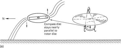
Figure 7.5(a) shows a helicopter which has just taken off and is accelerating forwards. The rotor thrust is inclined well forward and is accelerating the machine in a horizontal plane. The helicopter hangs from the rotor head like a pendulum, and the compass disc CM hangs from the pivot in the same way. As a result the compass disc in a pure helicopter usually stays very nearly parallel to the cockpit floor. The effect of the tilted disc during acceleration depends on the direction of flight and the hemisphere in which the machine is flying. If the machine in the example were to be heading 000°M the disc tilt will be in the same direction as the dip and there is no effect. However, in the example here the machine accelerates along 270M and the disc is inclined west down/east up. The vertical component of the earth’s field will rotate the north pole of the disc downwards and increase the heading shown against the lubber line. In the southern hemisphere, or if accelerating east, the opposite effect is obtained and the heading shown will reduce. On the equator the effect is absent.
Acceleration in the horizontal plane will also occur in a banked turn, which is the only kind of turn a helicopter can make at speed. Figure 7.5(b) shows a helicopter in a sharp bank to port. As the nose of the machine passes through magnetic north the acceleration is to the west and the disc tilts west down/east up. The vertical component of the earth’s field once more rotates the disc down at the north pole and increases the heading displayed.
|
|
|
|
(b)
Fig. 7.5 (a) When a helicopter accelerates at 270M in the northern hemisphere, dip will pull the north pole of the compass down and increases the apparent heading. (b) In a sharp bank there will also be acceleration towards the centre of the turn and a further acceleration error will occur.
Erroneous explanations will be encountered attributing some of the rotation of the compass disc to the acceleration alone, but a moment’s thought will confirm that a couple cannot be conveyed through a single pivot. It is almost certain that there will be a question on compass acceleration errors in one of the pilot’s examinations, and the correct answer will be obtained following the process below:
(a) Visualize the manoeuvre and the attitude of the rotor disc. The compass disc will be very nearly parallel to the rotor disc.
(b) If the disc is tilted north down/south up or vice versa there is no effect. If the tilt is east down/west up or vice versa there will be an error.
(c) Visualize the tilted compass disc in the earth’s dipping magnetic field. In the northern hemisphere the north-seeking pole dips; in the southern hemisphere the south-seeking pole dips.
(d) The dip will turn the tilted disc. Visualize whether this increases or reduces the heading read off against the lubber line.
Here is an example: a machine turns to port through north in the southern hemisphere. The rotor disc and compass disc will be tilted down on the west side, so the dip in the southern hemisphere will pull the south-seeking pole down. The compass disc is turned clockwise when seen from above. This causes the heading in degrees to be less than it should be. The pilot should turn to a greater reading or ‘overshoot the turn’ to compensate. In practice the error is countered by turning to a greater or a lesser indicated heading that will become the correct heading when the turn ceases and the compass settles.
In most cases the machine will have a gyroscopic direction indicator (see section 7.12) set to the same heading as the compass during steady flight. The direction indicator is used for turns because it does not suffer from acceleration errors so it is only necessary to invoke the theory if the DI fails.
In everyday use there is very little that can go wrong with a compass. It should be inspected for leaks of the liquid, for bubbles or for some obvious broken or cracked component, and if the transparent housing is plastic, this may darken as the material degrades with age and indicates that it is becoming brittle as well as difficult to see through. The deviation card must be present and the machine must have been swung on the appropriate occasions.
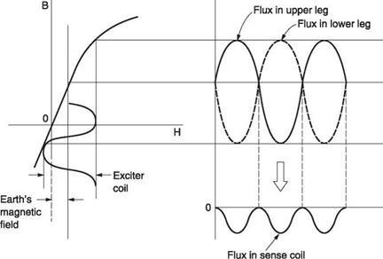
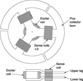
Figure 7.6(a) shows how a flux gate compass works. There are three radial pole assemblies and the side view shows that these are split so that a single coil with a vertical axis can be wound at the centre. There are a further three coils, one on each limb. The pole pieces are made of a highly permeable material such as permalloy. The entire assembly is suspended below a Hooke joint so that in steady flight it will hang level. An alternating excitation signal, typically 400 Hz, is applied to the central coil. In the absence of any external magnetic field, there would be no signal induced in the three sense coils because they are wound around both poles and the flux from the excitation coil would cancel out. However, in the presence of the earth’s magnetic field, the highly permeable material is more prone to saturation in one direction than the other. Figure 7.6(b) shows that the earth’s field adds to the excitation and shifts the operating point along the characteristic curve of the magnetic material. It will be seen in Figure 7.6(b) that the curvature of the magnetization characteristic has the effect of asymmetrically compressing the flux waveform so that there is a resultant flux in the sensor coil. The relative amplitudes of the three alternating signals induced in the sensor coils are a function of the direction of the earth’s field.
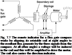
The three signals are sent to any remote instrument needing magnetic heading information. This could be a simple display or a tied gyroscopic DI. Figure 7.7 shows how a remote display works. The three signals from the flux gate are supplied to three coils arranged at 120°. There is also a second single coil that can rotate with respect to the three input coils. The resultant of the flux produced by these three coils will have a direction determined by the direction of the earth’s field at the sensor. As this is an alternating flux it will induce a voltage in the secondary coil. However, if this coil is exactly at right angles to the resultant flux, no voltage will be induced.
Figure 7.7 shows that the secondary coil signal is connected to an amplifier that drives a motor to turn the secondary coil and the display card. The amplifier will drive the motor until the secondary coil is transverse to the resultant field of the three input coils. At this point the induced signal will disappear and the motor will stop. Thus as the magnetic heading of the machine changes, the signals from the flux gate change the resultant flux direction in the display. The secondary coil is driven until it once more is in a null. In this way the motor and secondary coil follow the angle of the earth’s field with respect to the flux gate.
The flux gate compass has no controls and can be mounted anywhere convenient. In a fixed-wing aircraft the wing tip is a favoured location as it is well away from heavy ferrous objects. In a helicopter the tail boom could be used. Some flux gate compasses contain additional coils fed with carefully calibrated currents from a control box in
|
|
|
 |
order to cancel out deviation. In this case during swinging of the compass the goal is to find the correct values for these currents.
It is also possible to remove the variation in the earth’s magnetic field and obtain a true heading rather than a magnetic heading. This requires a device called a differential transmitter. This contains two sets of windings at 120°, but one set can be turned by an operator control. If the two sets of windings are aligned, the relative amplitudes of the signals coming out will be the same as those entering, but if the secondary winding is turned, the output signals are effectively rotated. Thus if the differential transmitter is set to the amount of local magnetic variation, the remote display will read true heading.
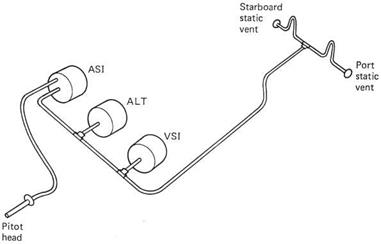
The instruments operated by pressure are the altimeter, the vertical speed indicator (VSI) and the airspeed indicator (ASI). Of these, the first two measure static pressure piped to the instruments from the static vents, whereas the ASI measures the dynamic pressure due to motion sensed as the pressure difference between the pitot head and the static vents. The necessary pipework is shown in Figure 7.8. The static vents are usually installed one each side of the fuselage in order to cancel any effect due to asymmetrical airflow. Each carries a mandatory placard stating that the vent is to be kept clear. The static pipes initially run upwards from the vents to prevent the entry of water.
The pitot head is installedfacing forward at some point where the airflow is reasonably undisturbed. It may be heated to prevent icing. The pitot should be checked for blockage as part of the pre-flight checks. It is good practice to cap the pitot with a suitable cover when the machine is on the ground, in which case the checks will include the removal and stowage of the cover.
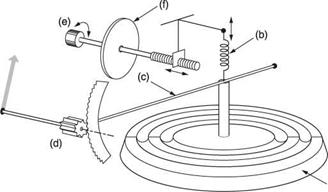
The altimeter is to all intents and purposes an aneroid barometer. The mechanism is shown in Figure 7.9. It contains a sealed capsule that is corrugated to allow it to flex. The capsule is evacuated, hence the term aneroid, and so ambient pressure attempts to crush it. The stiffness of the corrugations and a separate spring oppose the pressure. The capsule will expand as ambient pressure falls with rising altitude, and a system of
|
Fig. 7.8 The pipework involved with pressure-sensing instruments. These require a dynamic pressure feed from a forward facing port or pitot head and a static pressure feed typically from ports on the side of the hull. |
|
Fig. 7.9 iter is essentially a barometer fitted with a control that can adjust the reference. This allows it to display altitude with respect to a pressure that has been input on the setting scale. Evacuated bellows (a) is sensing element in conjunction with spring (b). Rising air pressure collapses bellows and stretches spring. Falling air pressure allows the spring to expand the capsule. Capsule movement is amplified by lever (c) which operates the display pointers via a system of gears (d). Altimeter is compensated for ambient pressure by turning knob (e) according to subscale setting required on the card (f). Subscale knob is arranged to stretch or relax the spring slightly in order to give zero reading at a range of barometric pressures. The case of the instrument is connected to the static vent pipe. |
links and gears amplifies the small capsule expansion to move the pointer over a scale. The aneroid altimeter needs no power except to illuminate the scale.
A conventional barometer measures absolute pressure for meteorological purposes, whereas the altimeter is required to measure the pressure difference between its present location and some reference pressure in order to compensate for barometric changes. The pressure difference is, however, displayed in feet (or metres). The reference pressure is set by the use of a control knob. Turning the knob will simultaneously change the reference pressure displayed on the subscale and the aneroid capsule spring tension.
If, for example, the reference pressure is to be raised, the act of setting the higher pressure on the subscale slightly extends the spring and the capsule will reach equilibrium showing a higher altitude. Conversely if a lower reference pressure is to be used, the spring is allowed to contract slightly and the capsule reaches equilibrium with a lower altitude reading. Throughout this process the absolute pressure at the altimeter did not change, but the pressure difference and the altitude did because the subscale setting was changed. Clearly without an appropriate subscale setting an altimeter reading is meaningless. It should also be clear that, in general, height and altitude are different.
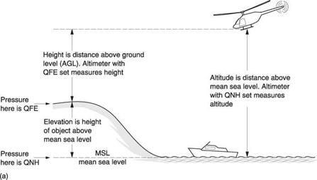
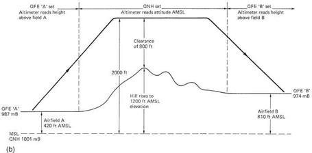
There are three main subscale settings used with an altimeter and these are shown in Figure 7.10(a). If the subscale is set to the ground pressure at the elevation of the airfield, the altimeter will read zero prior to take-off and in flight will measure height above the airfield. The barometric pressure at an airfield is called QFE. The ‘Q’ dates from the days of carrier wave radio and Morse code and indicates a question. An aircraft arriving at an airfield may ask for QFE in order to set the altimeter subscale so that the altimeter reads height above the field. QFE is easily remembered as ‘field elevation’. In some parts of the world this technique is not used. For example, the QFE of a mountain airfield may be so low that it is beyond the end of the altimeter subscale.
During a flight at moderate altitude the overriding concern is clearance of terrain and structures. These are quoted on maps as height above mean sea level (AMSL). In order to establish the clear height above such obstacles the altimeter reference is set to QNH; the barometric pressure in the area ‘reduced to mean sea level’. This means that the actual barometric pressure is measured at a known elevation and the value the pressure would have had at sea level is computed from the height and temperature. With QNH on the subscale, the altimeter reads feet AMSL and subtracting the height of obstacles in feet AMSL gives the clearance. QNH is easily remembered as ‘nautical height’.
Figure 7.10(b) shows a typical low-level flight. The machine takes off with QFE in the subscale to show height above the airfield. Once away from the field the altimeter is set to regional QNH and the machine is trimmed to cruise at 2000 feet AMSL. On the chart is a hill rising to 1200 feet AMSL and the machine will clear it by 800 feet. On approaching the destination airfield, the pilot asks for QFE and sets this on the altimeter. This should read zero as he touches down.
Each country is divided up into altimeter setting regions which each have their own QNH value as a function of the weather system across the country. The QNH quoted takes into account the rate at which barometric pressure is changing. If pressure is falling, a machine flying at constant pressure altitude based on QNH would actually descend and not have the expected clearance. QNH is adjusted upwards by the authorities to ensure that clearance is still achieved at the end of the period for which a setting is valid even if barometric pressure falls. On a long flight an altimeter setting region boundary may be crossed. The pilot must obtain the new QNH for the area to ensure his altimeter still reads feet AMSL. The subscale is generally calibrated in millibars (mb) or, more recently, hectoPascals (hP) that are numerically identical. In America, scales calibrated in inches of mercury (inHg) will be found.
For flight in airways, the overriding concern is not terrain clearance, but vertical separation between aircraft. For this reason the same reference pressure is always used in airways. This is the pressure of the International Standard Atmosphere (ISA) at Mean Sea Level (MSL): 1013.25 mb. Older texts may use the term QNe to describe this pressure. Aircraft flying with ISA on the subscale are flying at pressure altitude. The flight level is the pressure altitude with the last two digits removed. For example,
|
|
|
Fig. 7.10 (a) QFE is the local barometric pressure at ground level at an airfield. When the subscale is set to QFE, the altimeter reads height AGL (above ground level). (b) Once away from an airfield, the altimeter may be set to QNH. This is local pressure reduced to MSL (mean sea level) and the altimeter reads height above MSL. As obstructions on maps are described by their height AMSL, the QNH setting allows the pilot to establish that terrain clearance exists. QFE may be used for landing. This may be different from the QFE that was used at take-off. |
an aircraft at FL 350 is 35 000 feet above ISA MSL. Another aircraft at FL 340 would always be 1000 feet lower whatever the atmospheric conditions. Very few helicopter operations take place in airways, although as tilt-rotor and tilt-wing machines enter service this will change.
It should be noted that helicopter altimeters only sense local atmospheric pressure when the rotors are not turning. In the hover, especially in ground effect, the pressure under the rotor disc will be appreciably above ambient. Going from flat pitch on the ground to a low hover will result in a noticeable reduction in the reading on the altimeter, of the order of 30 feet. The effect is negligible in translational flight.
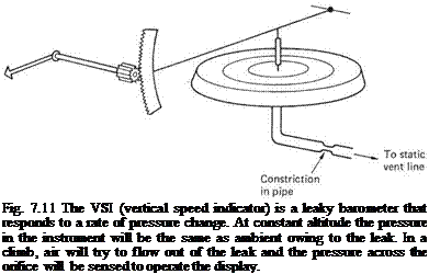 |
As its name suggests, the vertical speed indicator (VSI) displays the rate at which altitude is changing. Whilst this can be established by looking at the speed with which the hand of the altimeter turns, this takes some time and it is quicker to look at a separate display. Figure 7.11 shows how the VSI is constructed. The case of the instrument is connected to the static port of the aircraft. The mechanism includes a thin metal capsule sealed except for a very small orifice of carefully determined size. Should the aircraft climb, ambient pressure will fall and the capsule will expand, moving a pointer across a scale. The reduced ambient pressure will cause the air inside the capsule to flow out, but the flow is slowed down by the restriction. At constant altitude, the capsule will eventually have the same pressure inside and out, and the pointer will read zero. The faster the ambient pressure changes the more the restriction opposes the balancing airflow and the greater the deflection of the pointer. As it is self-balancing the VSI needs no pilot adjustment and has no controls. The VSI is particularly useful in cruise where it should read zero. Any discrepancy indicates that the helicopter needs retrimming to fly at constant height.
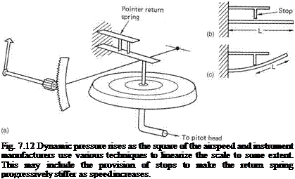
The airspeed indicator (ASI) is connected between the forward facing pitot head and the static vents. This arrangement cancels ambient air pressure so that it measures only the dynamic pressure due to forward flight. Dynamic pressure is proportional to air density and to the square of the velocity. As a result the expansion of the pressure-sensing capsule is proportional to the square of the speed, and it is necessary to convert the square law response to drive a practical scale. Figure 7.12 shows that this can be done using a straight spring (a) whose effective stiffness increases with deflection. At low speeds the whole length of the spring is active (b) and the restoring force is relatively low. When the spring contacts a stop (c) the active length is reduced and the spring becomes stiffer.
The system does not achieve complete linearity. Practical ASIs have decidedly nonlinear scales and the designer positions the stretched part of the scale at the most useful
range of flying speeds. In a light helicopter the stiffer spring may come into operation at about 100 mph. Pointer movement from 70 to 80mph may be twice that from 100 to 110 mph. A further consequence of the square law is that the dynamic pressure at low speed is very small indeed and comparable to the friction in the linkages. The ASI is unreliable at low speeds because of the low dynamic pressures involved and because of the effect of downwash. Thus an ASI generally has no calibrations below 20 mph. According to the country of origin ASIs will be found calibrated in mph, knots and kph, some have dual scales like car speedometers.
The reading of the ASI is also proportional to air density, so it will underread at high altitude. The scale on the ASI displays indicated air speed (IAS) proportional to density and the square of the speed. Since the rotors behave proportionally to these parameters, IAS is the best way of displaying speed from the point of view of the airframe. Clearly IAS is not the actual speed through the air, and for navigational purposes it needs compensating for ambient density to give true air speed or TAS. Density is affected by altitude and temperature. At 10 000 feet the IAS must be increased by around 17% to compensate for density change. An increase of 10° C raises TAS about 2%. If TAS, windspeed and direction are known, the groundspeed (GS) can be calculated.
In real ASIs the scale markings are not perfect, and frequently the position of the pitot head with respect to the hull causes errors at certain airspeeds. A calibration table is supplied so that IAS can be corrected by looking it up on the table. The result is called rectified or calibrated airspeed (RAS or CAS) and is the value the IAS would have read if it were free of error. In a helicopter airspeed is relatively slow and uncertainty about windspeed causes more error than the ASI. In this case it is probably not worth correcting the ASI for navigational purposes.
Airspeed and altitude are both sensed by measuring pressure, one dynamic and one static. Both of these processes are often combined in a single unit. As was seen above, pressure is measured using the deflection of a corrugated capsule. The amount of
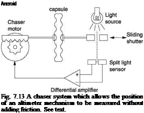 |
movement and the power available is small and it is difficult to drive a conventional encoder directly. Instead a form of electromechanical amplification is used. Figure 7.13 shows one example. The sensing capsule is mounted on a platform that can be moved by an electric motor. The moving diaphragm of the capsule carries only a low mass vane or plate placed in a light beam. The light falls on differential photocells so that very small off-centre movements of the diaphragm produce an electrical signal because more light falls on one cell and less on the other. This signal is amplified and supplied to the electric motor such that the motor is driven in a direction that recentres the optical sensor. Alternate types of sensing may be used, for example a differential transformer as will presently be described.
A motor used in this way is known as a chaser. Effectively the chasing action means that the diaphragm of the capsule remains in the same place. Pressure changes must then be reflected in the position of the motor drive, which has enough power to drive the pressure encoder. In addition to the encoder output, the speed of the motor may be measured to produce a rate output. When used for the altitude hold function in an autopilot, the chaser motor may be disconnected and the signal from the optical sensor will be used to make the aircraft climb or descend as needed to maintain altitude.
Altitude is sensed using an evacuated capsule, and means are required to allow the appropriate reference pressure to be set. Airspeed is sensed using a capsule exposed on one side to dynamic pressure at the pitot head and to static pressure on the other.
For automatic approach or landing systems a RADAR altimeter is a necessity. In fact it is not an altimeter as it does not consider air pressure; it is a height meter because it works by timing the reflection of a radio signal to give height AGL which is the requirement for landing.
Gyroscopic instruments are those depending on a rapidly rotating flywheel for their operation and include the direction indicator (DI), the turn and slip indicator (T + S), also known as the turn and bank indicator, and the artificial horizon. These display, in various ways, the attitude and heading of the helicopter. It is possible to fly a helicopter in good conditions without them, relying only on the magnetic compass for heading
information and assessing the attitude of the machine from the view of the world outside. In poor conditions or at night the horizon may be indistinct and without attitude clues even the finest pilot could lose control owing to disorientation. The gyroscopic instruments provide sufficient clues that in conjunction with the other flight instruments the machine can be flown without looking outside at all. Whilst the instruments are optional in a VFR light helicopter, most have them fitted and it is worth knowing how they operate as they could make a significant difference if an unanticipated deterioration in the weather takes place or if cloud is inadvertently entered.
The basic principle of the gyroscope was considered in Chapter 2. In practical instruments the gyro rotor is spun by an air jet or by an electric motor. Many light planes have a venturi in the slipstream that generates suction. This is applied to the case of the gyro instrument. Filtered cabin air is drawn into the instrument through a nozzle by the suction and blows the rotor round. Clearly this arrangement is not suitable for a helicopter as there is not necessarily a slipstream. A further alternative is to have a vacuum pump driven by the engine. The solution adopted in most helicopters is to drive the gyroscopes electrically. Power is fed through the gimbals by miniature sliprings.
As the operation of the gyro is dependent on the rotational speed, many gyros, but not all, have a flag coloured red or orange which swings into view if the rotor is not running fast enough. No flight action should be based on the reading of an instrument showing a flag.
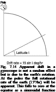
If a gyroscope is mounted in gimbals and set running with the rotor axis parallel to the earth’s surface, it will not remain in this condition due to drift. Drift has two unrelated components. First, the gyroscope is built to finite accuracy and minute imbalances in the gimbals and bearing friction will result in the spin axis changing slowly in an unpredictable manner; a genuine drift. Second, as the earth is turning at 15° per hour the gyro axis fixed in space will display apparent drift.
 |
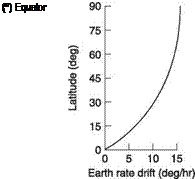 |
Figure 7.14 shows that the effect of the earth’s rotation on apparent drift is a function of latitude. At the equator the gyro axis and the earth’s axis are parallel and no drift is observed. However, at the geographic pole, the full 15°/hr will be observed. The apparent drift due to earth rotation is a sinusoidal function of latitude. The drift may
be modified if the gyro is in a moving aircraft. The track of the aircraft will have an east/west component and movement in this direction will have to be added to the rate at which the earth turns. This is known as transport error. The term transport wander will also be found, but this is misleading as the effect is entirely deterministic.
A completely free gyro will suffer from three forms of error: an unpredictable error due to non-ideal construction, and predictable errors due to the rotation of the earth and to being transported with respect to the earth. In a helicopter the low airspeed and relatively short flights mean that transport error is generally insignificant.
For earth-related activities such as flying, something will have to be done about drift. The solution depends upon the application, but essentially the rigidity of the gyro is used to offer short-term stability, whereas the long-term stability comes from elsewhere. A gyro externally stabilized in this way is described as tied. Where the long-term stability comes from the earth’s gravitational field, the result is called an earth gyro.
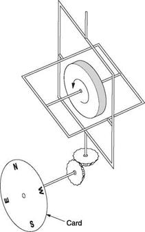
The direction indicator is a gyroscopic device that is designed to overcome acceleration errors in magnetic compasses and to be easy to read. Figure 7.15 shows the general arrangement of a DI. The rotor axis is maintained horizontal and the shaft is mounted in a pair of gimbals where the outer one pivots about a vertical axis. A gearing system couples the rotation of the outer gimbal to the disc or card visible to the pilot. If the
|
Fig. 7.15 The DI (direction indicator) is a gyroscopic instrument in which the gyro axis is maintained horizontal. As the aircraft changes heading, the gyro axis will remain the same and can drive a pointer to indicate the new heading. |
instrument is turned bodily about a vertical axis, the rigidity of the gyro will keep the gimbals fixed, and so the action of moving the instrument case around them will rotate the scale and indicate the angle through which the unit has turned.
The gyro axis is maintained horizontal by tying the gyro to the vertical gimbal ring. In an air-driven gyro there is already a stream of exhaust air leaving the rotor shroud. In an electrically operated gyro the rotor can be designed to act as a blower to produce an air jet. The air stream from the shroud impinges upon a wedge-shaped plate on the vertical gimbal ring. If the gyro axis (or the horizontal gimbal ring) is not at right angles to the vertical ring, the airflow will produce an imbalanced force on the vertical ring, tending to turn it. The direction of this force is such that it will cause the gyroscope slowly to precess in a direction that will bring the inner ring to rest at 90° to the outer or vertical ring.
As a result the gyro axis is aligned with the long-term average attitude of the helicopter about the roll axis. Compared to the slow rate of precession in the tying process, manoeuvres of the helicopter are very rapid and average out. In flight a turn would be accompanied by banking, but the gyro would maintain its axis because the inner gimbal can pivot in the outer.
Although more accurate in a manoeuvre than a magnetic compass, the DI does suffer from minor geometric errors. The outer gimbal has two sets of bearings at 90°, and essentially is acting as a Hooke joint between the gyro and the display card. As has been seen elsewhere in this volume, the Hooke joint is not a constant velocity joint, but suffers from cyclic angular errors when the input and output axes are not parallel. The result is that the DI reading is slightly out due to what is called gimballing error. It should be pointed out that gimballing error is very small and disappears when straight and level flight resumes.
The occurrence of gimballing error depends on the orientation of the gyro axis with respect to the helicopter’s yaw axis. In the general case where the gyro axis is not transverse to the flight path, a roll will cause gimballing error. In the special case where the gyro axis is transverse, a combined roll and pitch change will be needed to cause a gimballing error.
Figure 7.14 showed that with the DI gyro axis horizontal, the rotation of the earth causes apparent drift at a rate given by multiplying the earth rate, 15°/hr, by the sine of the latitude. For example, on the south coast of England at Lat. 51° N there will be a DI earth drift rate of just under 10°/hr.
In some units it is possible to compensate the DI for earth rate mechanically. The inner gimbal ring is deliberately imbalanced by a nut on an arm so that gravity produces a slight rolling torque on the gyro. The gyro will precess this into a yaw and when correctly adjusted the rate of yaw will be equal to the earth rate for the latitude at which the machine is normally operated so that the drift is cancelled. In more sophisticated DIs, there may be an adjustable earth rate compensator having a control which is set to the current latitude and a switch to select the sense of the compensation for the appropriate hemisphere. A latitude-dependent current is generated and sent to a torque motor in the DI fitted between the inner and outer rings. This applies torque to roll the inner ring, but the gyro precesses this into yaw. If the correct torque is applied for the latitude, the resultant precession rate will equal the earth rate and the DI drift will be minimal. In principle if the groundspeed, latitude and heading are known transport error can also be cancelled. This may be useful for flying near the magnetic poles.
However, most DIs rely on periodically being reset to the same reading as the magnetic compass and are fitted with a control knob which is pushed in and turned to force the gyro round to the correct heading. Pushing in the knob also forces the gyro axis to be at right angles to the vertical ring, a process known as caging. Clearly the machine
must be in steady flight when the DI is aligned to the compass or the gyro axis will be incorrect and it will be set to repeat the compass turning error.
More sophisticated DIs can tie themselves to a magnetic flux gate compass to produce a gyromagnetic compass which combines the best features of both devices. The flux gate compass was described in section 7.5. The tying process is heavily filtered so that compass errors during manoeuvres do not affect the reading. Gyromagnetic compasses have the advantage that they do not need to be reset.
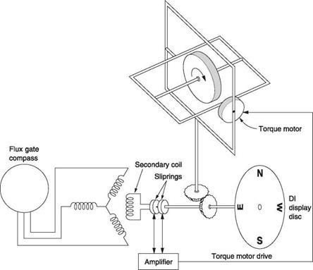
Figure 7.16 shows how the DI follows the magnetic compass. The signals from the flux gate compass are applied to a set of three coils encircling the shaft driving the display card in the DI. On the shaft is a single secondary coil. When the DI is accurately aligned with the compass, this coil will be transverse to the resultant flux of the three input coils and so no voltage will be induced in it. However, if any angular difference develops, a signal will be induced in the secondary coil and this can be amplified and used to drive torque motors that apply a rolling torque to the inner gimbal of the gyro. The gyro will precess this torque into yaw so that the display card will turn, and with it the secondary
|
Fig. 7.16 A slave DI that follows a flux gate compass. If the DI reading and the flux gate output are different, a torque motor precesses the DI until the two have the same indication. |
coil. In this way the gyro is precessed until the signal in the secondary coil nulls and the precession stops. At this point the display card will be showing the heading coming from the compass. The gain in the system will be quite low so that the gyro follows very slowly.
In some units it is possible to rotate the three coils using a front panel variation control so that the DI card reads true heading rather than magnetic. In most conditions tying the DI to magnetic north is useful, but when flying very close to the magnetic poles it may be better to turn the slaving off and to rely on the earth rate and transport error compensation only. A switch will be provided for this purpose.
A gyromagnetic compass may also form the heading reference for an autopilot. In this case the display unit has additional controls allowing the pilot to enter the desired heading. This is displayed with respect to the DI card markings by an indicator or bug on the periphery of the instrument. If the autopilot is engaged and a new heading is selected, the machine will carry out a two-minute rate turn to the new heading at which point the bug will align with the lubber line of the DI.
The artificial horizon is a gyroscopic instrument displaying a realistic copy of what the real horizon does for use in poor visibility. When the helicopter banks, the horizon in the display remains parallel to the real one. When the machine dives, the displayed horizon rises up the face of the instrument. A small symbolic aircraft on the face of the instrument then has the same attitude to the horizon as the real one, and if the pilot flies the symbolic aircraft the real one will follow. In a machine equipped with an autopilot, in addition to the visible display, the artificial horizon may provide attitude output signals that are fed into the control system to stabilize the flight attitude.
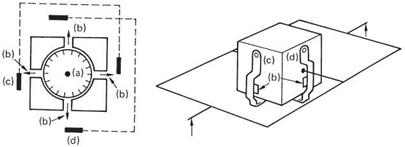
The gyroscope in an artificial horizon must be compensated for drift. This is done by an erection mechanism to maintain the axis of the gyro vertical with respect to gravity. For this reason, this type of instrument is sometimes called a vertical gyro. The addition of gravity sensing creates what is known as an earth gyro. Figure 7.17 shows how gravity sensing works. The rotating wheel is fitted inside a case. Two small pendula are fitted to the case in such a way that they can swing in orthogonal directions. The electrically driven rotor is fitted with vanes at one end so that it acts as a centrifugal blower. Air from the blower is arranged to leave the casing at four equally spaced points. Each pendulum has two vanes that block or reveal the blower orifices. The vanes are
|
Fig. 7.17 Gravity sensing is used in earth-tied instruments such as the artificial horizon. Small pendula (c) and (d) hang in the efflux (b) from a blower (a) built into the gyro rotor. If the rotor axis is not vertical the pendula will tilt and the reaction from the blower will be imbalanced so a precessive torque is created. |
arranged on opposite sides of the pendulum so that if the pendulum swings one way the area of one orifice is reduced whilst that of the other is increased; the situation is reversed if it swings the other way.
If the pendulum is central, the two orifices have equal areas revealed, and the thrust from the air jets will cancel. Should the gyro tilt with respect to gravity the pendulum will swing away from the centre position and the jet reaction will no longer balance. The net reaction is at right angles to the angular error, but this is exactly what is necessary as it causes the gyro to precess and right itself. As there are two orthogonal systems working simultaneously, the gyroscope maintains itself along the earth’s gravitational field. The erection system needs only to be able to work somewhat faster than the earth rate, and so the air jets do not need to be very powerful. In fact it is better if the erection process is slow because then momentary disturbances of the pendula caused by manoeuvres and turbulence are simply too rapid for the gravity-sensing system to respond to and they are filtered out. In some gyros the earth tying is done by tilt switches that operate torque motors acting on the gimbals. In more sophisticated instruments the erection process is switched off if the tilt switches tilt by more than a few degrees as this must be due to a manoeuvre.
As the gravity sensing is so subtle, a gyro takes about ten minutes to settle if started up with random orientation. In order to speed the process, the instrument is fitted with a caging knob that is operated when the aircraft is level. This operates a system of cams to force the gimbals back to the approximately correct attitude. When the cams retract, the gravity sensing finishes the job. The caging knob should not be operated when the machine is not level as a false attitude will be indicated. Gyros with tilt switch erection systems may have a fast erection mode for use on the ground or in level flight in which the precession rate is increased.
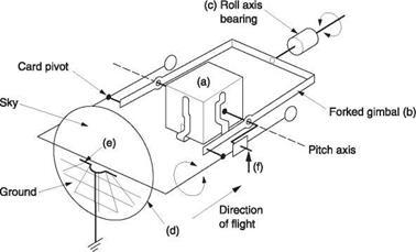
Figure 7.18 shows the general arrangement of the artificial horizon. The outer gimbal is pivoted on the roll axis of the aircraft and the inner gimbal is pivoted on the pitch axis. The gyro axis is vertical. Movement of the inner gimbal relative to the outer operates
|
Fig. 7.18 In an artificial horizon, a gravity-sensing gyroscope (a) is mounted on a forked gimbal (b), which is free to turn in the roll axis bearing (c). If the machine rolls, the horizon on card (d) will remain horizontal. If the machine pitches, the card and gyro will remain vertical, but the card will move in the viewing window with respect to the symbolic ‘wings’ (e). The crank (f) reverses the sense of the card movement so that when the machine dives the ‘ground’ on the card moves up. |
levers to move a large card painted with the earth at the bottom and the sky at the top. In a dive the instrument is tipped nose down and this causes the horizon card to rise with respect to the symbolic aircraft. In a climb the card falls. During a roll the outer gimbal remains horizontal, as does the horizon card. The instrument effectively banks around the card.
Clearly if a gyroscopic instrument is to work properly it must be fitted in the helicopter with the correct orientation, which is usually with the instrument face vertical. The artificial horizon is particularly sensitive to mounting attitude and if fitted to a sloping instrument panel a wedge plate is used to keep the instrument level. Certain artificial horizons can be adapted to work on a sloping panel. The card linkage is offset and the caging cam is turned around the inner gimbal by the angle of tilt so that the gyro remains vertical with the instrument tilted and the horizon in the centre of the display. In a helicopter the attitude of the machine about the pitch axis depends on forward speed. At high speed the nose down attitude would fool the instrument into thinking the machine was diving. To overcome this, the symbolic aircraft is fitted with an adjusting knob that allows it to be moved up or down slightly so that at the chosen airspeed it can be set to the displayed horizon.
The gyroscope can only maintain its rotational axis if the gimbals allow it sufficient freedom. This is true for moderate manoeuvres, but not for aerobatics. If a machine equipped with an earth gyro performs a quarter loop so it is going straight up, the two gimbals will become parallel and there will only be one degree of freedom. If, as this condition of gimbal lock is approached, the machine also rolls, there will be violent precession known as toppling as the gyro attempts to conserve momentum without the necessary freedom. After toppling, the gyro will be useless until it has erected again. If a gyroscopic instrument is expected to operate under aerobatic conditions, it will need additional outer gimbals. These are servo driven from sensors on the inner gimbals so that the latter are maintained at right angles at any attitude so that gimbal lock can never occur.
The turn and slip indicator is actually two completely independent instruments but combined in one housing as the two would be used together to make a turn. Figure 7.19 shows the mechanism of a turn indicator; actually a rate gyroscope. There is only one gimbal pivoted on the fore-and-aft axis of the helicopter and the gyro shaft is transverse. The gimbal is held central by a light spring and rocking of the gimbal moves a pointer over a scale. If the helicopter turns, the gyroscope precesses and rocks the gimbal. The faster the turn, the further the precessing gyro will be able to extend the centring spring. A small dashpot is provided to damp the motion of the rocking gimbal. This may consist of a piston sliding inside a cylinder having a small air bleed hole at the end. This reduces pointer movement due to vibration or turbulence and displays the average turn rate only. Helicopter turn indicators are generally designed to reach a scale mark at a rate of 180° per minute, corresponding to the two-minute turn rate commonly used in instrument flying. As the gyro is controlled by the centring spring, no action is needed to compensate for earth rate and the instrument has no controls.
The slip indicator is no more than a weight in a fluid filled curved glass tube. In a correctly banked turn, the apparent gravity should remain perpendicular to the cockpit floor and the weight stays in the centre of the curved tube at the lowest point. If the amount of yaw does not match the amount of bank, there is sideslip and this causes the weight to slide away from the centre of the tube. Figure 7.20 shows that, in a fixed-wing
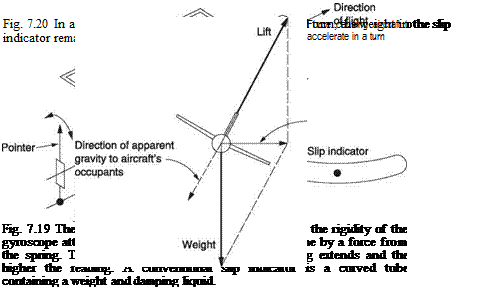 |
aircraft in a properly co-ordinated turn, the acceleration into the centre of the turn and the acceleration due to gravity combine to give an apparent gravity in the cockpit that is straight down through the floor. Thus it is possible to use a damped pendulum as a slip indicator.
As was seen in section 5.2, the conventional helicopter cannot balance main rotor torque with the tail rotor alone. There has to be another force in conjunction with the tail rotor in order to create a couple. In forward flight this may come from a slight rotor tilt or from side slipping the hull or from some combination of both. The least drag is obtained with zero slip, but in many helicopters the zero slip condition results in a hull
that is not level in straight flight. If the slip indicator is installed vertically with respect to the hull, and if the machine is flown with the slip ball centred, the result may be sideslip, increased drag and a navigational problem because a side slipping machine is not going the way it is pointing. In addition, certain conditions of fuel level or loading may cause the CM of the machine to be offset to port or starboard of the centreline. This will further affect the slip gauge.
An autopilot needs to sense the attitude of the helicopter in each axis being stabilized, and the rigidity of the gyroscope makes an excellent attitude reference. In some cases it is possible to use the existing vertical axis gyroscope in an artificial horizon to provide pitch and roll data for an autopilot. When this is done, in addition to driving the visual display the gyro contains encoders to provide electrical signals proportional to the amount of pitch and roll.
Where high accuracy is required, a separate gyro having no display but providing attitude signals only can be used. Clearly the location of such a device in the airframe is subject to a good deal of freedom. If an inertial navigator is carried, the inertial platform must be tied to the earth and so can act as a reference to provide attitude signals in all three axes. The attitude data may be sensed by synchro generator or by digital encoder, according to the signalling technology used.
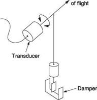
Automatic turn co-ordination in forward flight requires essentially a slip ball with an electrical output. This is the function of a device known as a dynamic vertical sensor. Figure 7.21 shows that it consists of a pendulum whose axis is fore and aft and which carries a transducer such as a synchro or other encoder. The pendulum will be damped against turbulence and vibration. In a correctly co-ordinated turn the pendulum will not move with respect to the sensor because the direction of the acceleration will be along the pendulum axis.
An alternative to the dynamic vertical sensor is to use a vane-type sensor to measure the direction of motion of the hull through the air.
|
Direction
Fig. 7.21 The dynamic vertical sensor is essentially a slip indicator with an output signal. It consists of a damped pendulum having a transducer. |
The helicopter differs from the fixed-wing aircraft in that it can move in virtually any direction in three dimensions and at very low speeds. This makes airspeed measurement difficult. The conventional ASI with its pitot head is only accurate when the relative airflow approaches within 10-15° of the straight-ahead position. At greater angles, the pressure caused by flow of the rotor downwash around the hull may result in major errors, especially at low speeds where the dynamic pressures due to airspeed are very low. Helicopter pilots learn to treat ASI readings with suspicion or even amusement at low speeds especially when hovering in cross – or tail-winds.
With a conventional ASI, it is impossible to establish if a zero-airspeed condition exists, yet this is important to helicopter operations because of the possibility of entering a vortex-ring condition. Another requirement for accurate low airspeed information is in systems that control automatic stabilators. Special sensors have been developed for helicopters to overcome some of these difficulties.
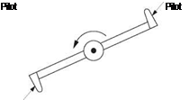
Figure 7.22 shows a system that can measure horizontal airspeed in any direction. This consists of a rotating assembly with pitot heads on each end of an arm. The assembly can be mounted above the rotor to turn with it, or on the hull and turned by a motor. The dynamic pressure will only be constant if the horizontal airspeed is zero. In all other cases there will be a sinusoidally varying difference in dynamic pressure between the two pitots. The amplitude will represent the airspeed and the phase with respect to the rotational phase of the arm will represent the direction. A twodimensional indicator may be used to display the fore-and-aft and lateral components of airspeed.
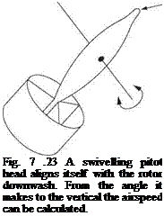
Figure 7.23 shows an alternative system consisting of a small finned swivelling body that will align itself with the downwash. This contains a pitot to measure the downwash velocity. From the downwash velocity and the angle of the body it is possible to compute the horizontal component of the downwash and this is the airspeed.
 |
The slip string is a simple piece of string attached to the centre of the windscreen. If the machine is being flown without slip, the string will align with the airflow and take on a vertical attitude. If there is any slip the string will turn. Despite its apparent crudity, the slip string is a useful device because it does not suffer from the problems of the pendulum-based slip indicator. A machine flown with the slip string centred will have lower drag than one flown with the slip ball centred. This may be significant if power is limited. The machine will also fly along its heading, making navigation easier.
Fig. 7.22 A rotating airspeed indicator that can measure airspeed in any direction down to zero. The difference between the dynamic pressures at the two pitot heads determines the airspeed. The phase of the dynamic pressure signals with respect to the rotation reveals the direction.
In a fancy version of the slip string, a small weathervane on the nose of the machine having an angular sensor drives a slip meter on the instrument panel.
The principle of radio direction and ranging (RADAR) is simply the analysis of reflected radio waves. In active RADAR, the radio signals are generated at the analysis equipment, whereas in passive RADAR signals may come from other sources. Radio signals are electromagnetic waves and these have the characteristic the way they interact with objects is a function of the relative size of the object and the wavelength. Very long wavelengths simply diffract around objects returning very little energy to the transmitter, whereas short wavelengths are reflected more efficiently, hence the use of short wavelengths in RADAR.
Figure 7.24 shows that two variables can be extracted from returned radio signals. At (a) a pulse is transmitted and the time taken for the reflection to arrive will allow the distance to the target to be computed. At (b) a continuous signal is transmitted and any relative velocity between the target and the transmitter will cause the frequency of the return to be shifted by the Doppler effect.
The RADAR altimeter is based on the first principle. Despite its name, it is not an altimeter. The transmitter and receiver are directed downwards and the signal reflected from the earth is used to compute height above ground, not altitude. This is extremely useful for terrain avoidance and for landing in poor conditions and may be used as the actual height input to an altitude hold system.
RADAR altimeters have some limitations. When flying over a tree canopy, the reading may be anywhere between ground level and treetop height. When flying with an underslung load, the RADAR altimeter may measure the length of the load cable.
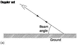
Figure 7.25 shows how a Doppler RADAR works. The received signal is amplified and multiplied by the transmitted signal in a mixer. Any difference in frequency between the transmitted and received signals will be output by the mixer. This frequency is proportional to the axial component of relative velocity between the transmitter and the target. Figure 7.26(a) shows that as a practical matter, an airborne Doppler RADAR must use a transmitted beam which is angled downwards. The forward motion of the helicopter is not in the same direction as the beam. The system will measure the actual
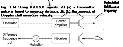 |
Fig. 7.25 Doppler RADAR mixes the transmitted and received signals to create a difference frequency proportional to target velocity.
ground velocity multiplied by the cosine of the beam angle. A signal processor in the Doppler receiver can make the necessary correction.
If two orthogonal (mutually at right angles) beams are transmitted, it will be possible to resolve the angular difference between heading (direction of travel through the air mass) and the track (direction of travel over the ground) from the relationship between the two Doppler velocities. If this information is compared with the true airspeed and the heading it will be possible to compute the wind velocity.
Manoeuvres will result in the angle of the beams changing with respect to the earth and this must be compensated using attitude signals from a vertical gyro or with a third beam.
Another useful characteristic of Doppler RADAR is that the number of cycles of the signal emerging from the mixer is proportional to the distance flown in the
 |
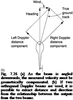 |
direction of the beam. If the heading output of a gyromagnetic compass is combined with the Doppler-derived track-to-heading angle, the true track can be computed. Figure 7.26(b) shows that during a flight in wind, the orthogonal Doppler beams will both output distance components. The resultant of the two will give the ground distance flown. This is the principle of the Doppler navigator that has the advantage of needing no earth-based signals whatsoever.
Control signalling is the process of communicating the position of a mechanism from one place to another. There are many applications of such signalling in a modern aircraft: the position of one of the pilot’s controls may be signalled to an actuator, the actual position of an actuator may be signalled to a feedback control system and the attitude of an artificial horizon may be signalled to an autopilot and to a RADAR set so that the attitude of the RADAR antenna remains stable during manoeuvres.
|
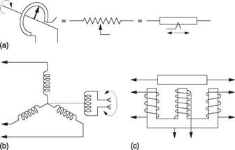
Fig. 7.27 Transducers used in signalling. At (a) the potentiometer or variable resistance. At (b) the synchro outputs three AC signals as a function of the rotor angle. The LVDT (linear variable displacement transducer) shown at (c) is a form of linear synchro. It has the advantage over the potentiometer that there is no sliding contact and no wear mechanism. |
Figure 7.27 shows some methods used for control signalling. At (a) is the potentiometer. This is a resistance that outputs a DC voltage proportional to the position of the moving contact or wiper. The potentiometer may be rotary or linear and is simple, but the sliding wiper introduces a wear mechanism. The remaining devices are more complex but wear free. At (b) is the AC operated synchro generator that signals rotational angle to a synchro motor using three wires. The synchro is ideal for measuring the angle of a joystick or side-arm controller or the reading of a compass. In the synchro there is a rotor carrying a single coil which is fed by sliprings and brushes. Surrounding the rotor is a set of three coils mounted at 120° in a star arrangement. The synchro works like a transformer in that it must have an alternating supply. Traditionally this will be the 400 Hz AC used in aircraft and the supply is fed to the rotor via the sliprings. The current flowing in the rotor produces a magnetic field at right angles to the rotor shaft. The voltage induced in each of the secondary windings depends on the angle of the rotor. If the field of the rotor were parallel to a given secondary, the induced voltage would be a maximum, but if the rotor were at 90° to that secondary the induced voltage would be zero. The induced voltage in a given winding is proportional to the cosine of the angle between the rotor and that winding. With three windings there must be a unique combination of voltages for any position of the rotor.
At (c) is the linear equivalent of the synchro which is the LVDT (linear variable displacement transducer). This is also fed with an AC excitation signal. The moveable core alters the magnetic coupling between a pair of input coils and the output coil. The input coils are connected in anti-phase and with the core in the central position the flux from these two is cancelled out. If the core moves off-centre the amplitude of the output increases in proportion to the displacement. The phase of the output represents the direction. A phase-sensitive amplifier can extract a voltage proportional to the position of the core. As the LVDT signals linear position, it is ideal for measuring the extension of an hydraulic ram or of a ball screw actuator.
The synchro motor is almost identical to the synchro generator. The main difference is that it contains a rotary damper to prevent it spinning like an electric motor. The
rotor of the synchro motor is fed with the same AC drive as the synchro generator by connecting the two in parallel. When the three windings of the synchro motor are fed with signals from a synchro generator, they produce a resultant flux direction with which the rotor aligns.
The synchro system is capable of high resolution but the synchro motor cannot develop much torque. If a significant load has to be positioned remotely, the synchro system will require power amplification. In this case the receiving device may be a control transformer. This is virtually identical to the synchro motor, the main difference being that the rotor winding is not connected to the AC supply but is instead connected to a phase-sensitive amplifier. Figure 7.7 showed the principle. A motor driving the load also turns the rotor of the control transformer. An amplifier senses the signal from the control transformer rotor and drives the motor.
The three signals from the synchro generator reproduce the flux direction of the generator’s rotor in the control transformer. If the rotor of the latter is at 90° to that flux direction it will produce no output. However, if there is a misalignment, say clockwise, the rotor will produce an output which is a sine wave in-phase with the signal exciting the synchro generator. However, if the misalignment is anticlockwise, the rotor output will be in anti-phase with the synchro generator input. The amplitude of the rotor output will increase with the angular error. The phase-sensitive amplifier drives an electric motor to move the load. Using the phase information from the stator, the amplifier can drive the load in the correct direction to make the angular error in the control transformer smaller. When the rotor of the control transformer is at 90° to the induced field from the three windings the rotor output disappears and the motor stops. In this way a significant load driven by a motor can be controlled remotely by the low power signal available from the synchro generator.
The potentiometer, the synchro and the LVDT are analog devices in that the signals they produce are infinitely variable. Instead of analog signalling, it is also possible to transmit control position numerically. In digital systems, a binary number proportional to the position of the control is encoded. All of these signals may be carried by electrical cable, leading to the marketing term ‘fly-by-wire’. Digital signals can also be carried along optical fibres, leading to the term ‘fly-by-light’.
Digital signalling is a technology that arrived in aviation quite suddenly and so there is no traditional knowledge or experience base. As a result many people regard digital signalling as little short of black magic when in fact it is based on relatively simple principles. One of the key concepts to grasp is that digital signalling is simply an alternative means of carrying the same information. An ideal digital signalling system has the same characteristics as an ideal analog system such as a synchro: both of them are totally transparent and remotely reproduce the original applied control movement with negligible error.
Although there are a number of ways in which the position of a control can be represented digitally, there is one system, known as pulse code modulation (PCM) that is in virtually universal use. Figure 7.28 shows how PCM works. Instead of being continuous, the time axis is represented in a discrete or stepwise manner. The control waveform is not carried by continuous representation, but by measurement at regular intervals. This process is called sampling and the frequency with which samples are taken is called the sampling rate or sampling frequency Fs. The sampling rate is generally fixed and is thus independent of any frequency in the signal.
|
9 10 10 7 4 З 3 5 -*—— Data to be stored or transmitted are whole numbers Fig. 7.28 In PCM or digital signalling, the position of a control is sampled periodically and the sample is expressed as a discrete number. |
Those who are not familiar with digital signalling may worry that sampling takes away something from a signal because it is not taking notice of what happened between the samples. This would be true in a system having infinite response rate, but no real control system can be like this. All control signals from joysticks, actuators, gyros etc., have a distinct limit on how fast they can change. If the sampling rate is high enough, a control waveform can only change between samples in one way. It is then only necessary to carry the samples and the original waveform can be reconstructed from them.
Figure 7.28 also shows that each sample is also discrete, or represented in a stepwise manner. The value of the sample, which will be proportional to the control parameter, is represented by a whole number. This process is known as quantizing and results in an approximation, but the size of the error can be controlled until it is negligible. If, for example, we were to measure the height of humans only to the nearest metre, virtually all adults would register 2 metres high and obvious difficulties would result. These are generally overcome by measuring height to the nearest centimetre. Clearly there is no advantage in going further and expressing our height in a whole number of millimetres or even micrometres.
The point is that an appropriate resolution can also be found for a control system, and a higher figure is not beneficial. If a conventional pushrod control system is considered, each bearing and joint in the system has some backlash and the cyclic stick on a typical helicopter can always move some small distance before any motion is detected at the swashplate. If the movement step size of a digital system is of the same order as the backlash of a mechanical system, both systems have the same accuracy.
The advantage of using whole numbers is that they are not prone to drift. If a whole number can be carried from one place to another without numerical error, it has not changed at all. By describing control parameters numerically, the original information has been expressed in a way that is better able to resist unwanted changes. The amount of backlash in a mechanical system increases with the number of ball joints and bell cranks in a control run. The accuracy of a mechanical signalling system would decline as
wear occurs. A digital system can transfer whole numbers from one end of the airframe to the other without any loss of accuracy at all and will not be affected by wear.
Essentially, digital signalling carries the original control parameter numerically. The number of the sample is an analog of time, and the magnitude of the sample is an analog of the value of the parameter. As both axes of the digitally represented waveform are discrete, the variations in the parameter can accurately be restored from numbers as if they were being drawn on graph paper. If greater accuracy is required, paper with smaller squares will be needed. Clearly more numbers are then required and each one could change over a larger range.
Humans expect numbers expressed to the base of ten, having evolved with that number of digits. Other number bases exist; most people are familiar with the duodecimal system using the dozen and the gross. The most minimal system is binary, which has only two digits, 0 and 1. BInary digiTS are universally contracted to bits. These are readily conveyed in switching circuits by an on state and an off state or in optical fibres by the two states of a light source. With only two states, there is little chance of error.
In decimal systems, the digits in a number (counting from the right, or least significant end) represent ones, tens, hundreds and thousands etc. Figure 7.29 shows that in binary, the bits represent one, two, four, eight, 16 etc. A multi-digit binary number is commonly called a word, and the number of bits in the word is called the word length. The right – hand bit is called the least significant bit (LSB) whereas the bit on the left-hand end of the word is called the most significant bit (MSB). Clearly more digits are required in binary than in decimal, but they are more easily handled.
The word length limits the range of a binary number. The range is found by raising two to the power of the word length. Thus a four-bit word has 16 combinations, and could set a control to only 16 positions. Clearly this would not be good enough for a flight control. However, a ten-bit word has 1024 combinations, which is close to 1000. A mechanical flight control that could be positioned to one part in a thousand would be considered remarkable.
In a digital signalling system, the whole number representing the value of the sample is expressed in binary. The signals sent have two states, and change at predetermined times according to some stable clock. Figure 7.30 shows the consequences of this form of transmission. If the binary signal is degraded by noise, this will be rejected by the
 This bit represents
‘1’
This bit represents
‘2’
Examples
01 0 12 = 510 1 1 1 12 = 1510 1 0 0 12 = 910
Fig. 7.29 Binary coding principles. See text for details.
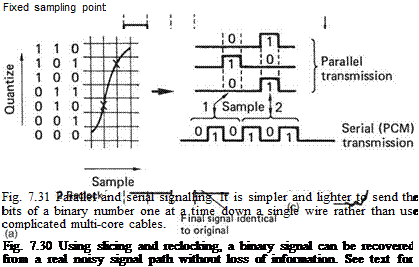 |
receiver, which judges the signal solely by whether it is above or below the half-way threshold, a process known as slicing. The signal will be carried in a channel with finite bandwidth, and this limits the slew rate of the signal; an ideally upright edge is made to slope. Noise added to a sloping signal can change the time at which the slicer judges that the level passed through the threshold. This effect is also eliminated when the output of the slicer is reclocked. However many stages the binary signal passes through, it still comes out the same, only later. Control samples represented by whole numbers can reliably be signalled from one place to another by such a scheme, and if the number is correctly received, there has been no loss of information en route.
There are two ways in which binary signals can be used to carry control samples and these are shown in Figure 7.31. When each digit of the binary number is carried on a separate wire this is called parallel transmission. The state of signal on the wires changes at the sampling rate. Using multiple wires is cumbersome and heavy, and a
|
Fig. 7 .32 A linear encoder in which the position of the moving part determines the binary code created. |
single wire can be used where successive digits from each sample are sent serially. This is the definition of pulse code modulation. Clearly the clock frequency must now be higher than the sampling rate.
Whilst control samples can be obtained by digitizing the output of an analog control such as a potentiometer, it is preferable to obtain samples directly in a digital encoder. Digital encoders are a form of displacement transducer in which the mechanical position of the shaft or pushrod is converted directly to a digital code. Figure 7.32 shows an absolute linear encoder. A grating is moved with respect to several light beams, one for each bit of the control word required. The interruption of the beams by the grating determines which photocells are illuminated. It is not possible to use a pure binary pattern on the grating because this results in transient false codes due to mechanical tolerances. Figure 7.33 shows some examples of these false codes. For example, on moving the fader from 3 to 4, the MSB goes true slightly before the middle bit goes false. This results in a momentary value of 4 + 2 = 6 between 3 and 4.
The solution is to use a code in which only one bit ever changes in going from one value to the next. One such code is the Gray code first devised to overcome timing hazards in relay logic but is now used extensively in position encoders. Gray code can be converted to binary in a suitable look-up table or gate array or by software in a processor.
For digital signalling, the prime purpose of binary numbers is to express the values of the samples representing the original control position. Figure 7.34 shows some binary numbers and their equivalent in decimal. The radix point has the same significance in binary: symbols to the right of it represent one-half, one-quarter and so on. Binary is convenient for electronic circuits, which do not get tired, but numbers expressed in binary become very long, and writing them is tedious and error-prone. The octal and hexadecimal notations are both used for writing binary since conversion is so simple. Figure 7.34 also shows that a binary number is split into groups of three or four digits starting at the least significant end, and the groups are individually converted to octal or hexadecimal digits. Since 16 different symbols are required in hex, the letters A-F are used for the numbers above nine.
There will be a fixed number of bits in a control sample, which determines the size of the quantizing range. In a ten-bit sample there may be 1024 different numbers. Each
|
Fig. 7 .33 The false codes created if pure binary is used in an encoder. See text for details. |
number represents a different control position, and care must be taken during encoding to ensure that the control does not go outside the quantizing range, or it will be limited or clipped.
In aviation many controls are bi-directional and have a centre neutral position. In Figure 7.35 it will be seen that in a ten-bit pure binary system, the number range goes from 000 hex, which represents the largest negative input, through 1FF16, which represents the smallest negative input, through 20016, which represents the smallest positive input, to 3FF16, which represents the largest positive input. Effectively, the neutral position of the control has been shifted so that both positive and negative inputs may be expressed as positive numbers only. This approach is called offset binary, and is perfectly acceptable where the control has been encoded solely for signalling from one place to another.
![]()
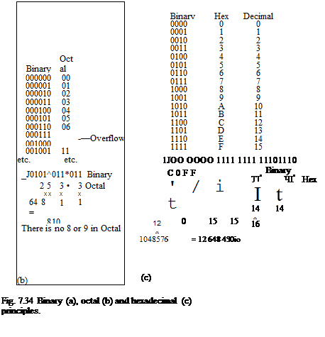 |
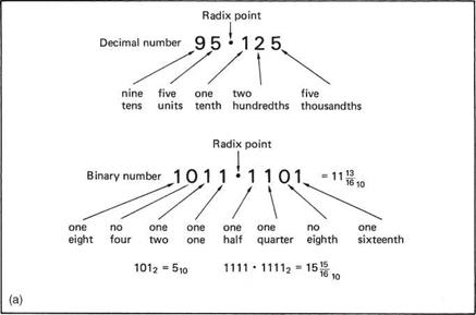
|
||
|
||

000-|6—— Largest negative displacement
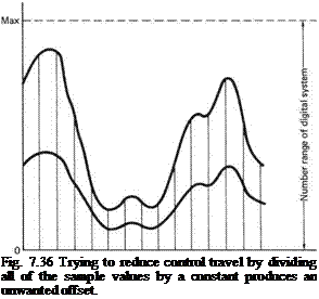 |
Fig. 7 .35 In a pure binary system, only positive values are possible. A bi-directional system can be obtained by adding an offset so that neutral is half-way up the scale.
In practice it may be required to modify the control samples between, for example, a joystick and the associated actuator. The control may prove too sensitive and by processing the samples a given movement of the joystick could be arranged to produce a smaller movement of the actuator, perhaps as a function of airspeed. A small number might be added to the samples to perform a trim function. Two control signals might be added together to mix cyclic and collective controls into the swashplate or to mix the output of a stability augmentation system or autopilot into the flight controls.
If two offset binary sample streams are added together in an attempt to perform digital mixing, the result will be that the offsets are also added and this may lead to an overflow. Similarly, if an attempt is made to reduce the sensitivity of a control by, say, half by dividing all of the sample values by two, Figure 7.36 shows that the offset is also divided and the waveform suffers a shifted baseline. The problem with offset binary is that it works with reference to one end of the range. What is needed for aircraft controls is a numbering system operating symmetrically with reference to the centre of the range.
|
Fig. 7 .37 Two’s complement coding. See text for details. |
In the two’s complement system, the upper half of the pure binary number range has been redefined to represent negative quantities. If a pure binary counter is constantly incremented and allowed to overflow, it will produce all the numbers in the range permitted by the number of available bits, and these are shown for a four-bit example drawn around the circle in Figure 7.37. As a circle has no real beginning, it is possible to consider it to start wherever it is convenient. In two’s complement, the quantizing range represented by the circle of numbers does not start at zero, but starts on the diametrically opposite side of the circle. Zero is midrange, and all numbers with the MSB set are considered negative. The MSB is thus the equivalent of a sign bit where 1 = minus. Two’s complement notation differs from pure binary in that the most significant bit is inverted in order to achieve the half circle rotation.
Controls having limited travel, such as potentiometers and LDVTs, can also have their outputs converted to two’s complement. Figure 7.38 shows how a real ADC (analog to digital convertor) is configured to produce two’s complement output from, for example, a potentiometer. At (a) an analog offset voltage equal to one-half the quantizing range is added to the bipolar analog signal in order to make it unipolar as at (b). The ADC produces positive only numbers at (c) which are proportional to the input voltage. The MSB is then inverted at (d) so that the all-zeros code moves to the centre of the quantizing range. The analog offset is often incorporated in the ADC as is the MSB inversion. Some encoders are designed to be used in either pure binary or two’s complement mode where the MSB inversion may be applied as required.
|
Fig. 7 .38 Producing two’s complement from real bipolar signals. At (a) an offset of half scale is added to the input. The offset input is converted (b) to pure binary. The MSB is inverted at (c) to produce two’s complement. |
The two’s complement system allows two sample values to be added, or mixed, and the result will be referred to the system midrange; this is analogous to adding analog signals in a synchro differential or adding pushrod movements in a mechanical mixer.
Figure 7.39 illustrates how adding two’s complement samples simulates the control mixing process. The waveform of input A is depicted by solid black samples, and that of B by samples with a solid outline. The result of mixing is the linear sum of the two waveforms obtained by adding pairs of sample values. The dashed lines depict the output values. Beneath each set of samples is the calculation that will be seen to give the correct result. Note that the calculations are in pure binary. No special arithmetic is needed to handle two’s complement numbers.
It is often necessary to phase reverse or invert a control signal, for example in a cyclic/collective mixer the lateral cyclic signal needs to be added to the collective signal on one side of the swashplate but subtracted on the other. Using inversion, signal subtraction can be performed using only adding logic. The inverted input is added to perform a subtraction, just as in the analog domain. This permits a significant saving in hardware complexity, since only carry logic is necessary and no borrow mechanism need be supported.
The process of inversion in two’s complement is simple. All bits of the sample value are inverted to form the one’s complement, and one is added. This can be checked by mentally inverting some of the values in Figure 7.37. The inversion is transparent and performing a second inversion gives the original sample values. When a binary counter is incremented it will eventually reach the all-ones condition. A further count will result in an overflow condition. For example, if a four-bit counter is at 1111 (15 decimal) an
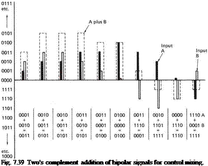 |
extra count will result in 10000 (16 decimal) requiring five bits. Clearly there is no facility to handle the leading 1 in a four-bit system and so the remaining four bits will all be zero. Consequently the count starts again. This gives a finite word length counter a circular structure allowing it to represent the operation of an angular sensor. Using finite word length binary, angular parameters such as magnetic heading, variation, and track angle can be incorporated in navigational computations.
Figure 7.40 shows the interior of an hydraulic power-assisted ram. The output rod carries a swinging arm operating the error valve. The input is connected to the arm by a ball joint. The error valve contains a pair of discs and is called a spool because it resembles a film spool. The spool controls the flow of fluid to the cylinder down passages in the pushrod. If the pilot moves a control such that the input moves to the left, the spool will slide left and the left disc will admit fluid under pressure to the right-hand side of the piston. The right disc will allow fluid from the left-hand side of the piston to return to the reservoir. The piston will move to the left under hydraulic pressure, but in doing so it will move the upper end of the input lever to the left, and will close the spool valve. In servo terminology, the linkage driving the spool valve is comparing the actual load position with the desired position to produce an error.
As a result of the error the output of the ram is made to follow the input. If the input reverses, the spool valve moves the other way and admits fluid to the other side of the piston. As the pressure is so high, only tiny discrepancies need exist between the input and output position for fluid flow to occur and so there is considerable loop
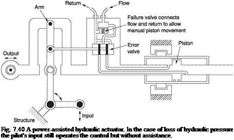 |
gain. Clearly the actuator body moves and the hydraulic supply needs to be fed through flexible hoses.
In hydraulic rams as the error becomes smaller the orifices through which fluid flows become very small and the viscosity of the fluid provides damping. When the error is zero the flow is negligible and the main ram is effectively locked because there is no path for fluid to pass around the piston. As a result hydraulic actuators tend to be self-damping and in simple systems no tachometer feedback is needed.
It will be seen from the figure that the flight load is shared between the ram and pilot effort by the proportions of the swinging arm. In the case of loss of pressure, the input lever moves until it comes into contact with stops on the piston rod. The input force is thereby transmitted to the output. The controls will be much heavier and will display a slight backlash, but they are still effective.
In a fully powered system a direct mechanical connection between the pilot’s controls and the load to be moved is pointless as without power the load could not be moved by the pilot alone. Instead the control signals from the pilot are compared with the actual position of the load, and any difference causes the power system to operate in such a way that the difference is minimized.
Figure 7.41(a) shows an example of a fully powered system in which a spool valve is operated by a balance lever which subtracts the load position from the commanded position.
Figure 7.41(b) shows a duplex actuator which consists of two hydraulic rams in tandem on a common pushrod. Each ram is supplied by a different hydraulic system. If pressure in one system is lost, the other ram can continue to provide control provided that the failed ram does not obstruct the working ram with an hydraulic lock. This can be arranged by providing valves to allow fluid to flow from one side of the piston to
|
|
|
(b) Structure Fig. 7.41 (a) A fully powered actuator which is needed for large machines where the pilot could not operate the controls unaided. (b) For reliability, fully powered actuators are duplicated with separate sources of hydraulic power. Note ram bypass valves which open if hydraulic pressure is lost, allowing the other system to move the piston. |
the other. This valve can be seen in the figure. When hydraulic pressure is available, the valve is forced shut, but if pressure is lost the valve opens so that the functioning actuator is not impeded.
In Figure 7.41 it would be possible to replace the pushrod from the pilot with some other type of signalling. If electrical signalling is used, the control ram will contain an electro-hydraulic valve (EHV) so that electrical signals can control the hydraulic power source. Figure 7.42 shows how an electro-hydraulic valve works. The valve is pulled or pushed by magnetic fields from the drive coils, and admits hydraulic fluid to the spool valve controlling the main ram. As fluid is allowed to flow, the resulting fluid pressure on the valve output is arranged to oppose the magnetic force. This tends to close the valve. Thus the fluid flow rate is made roughly proportional to the electrical current in the coil so the ram extends at a controlled speed.
Another possibility is for the mechanical pushrod input to an hydraulic actuator to be driven by a low powered electrically driven servo. This approach may be used in machines where stability augmentation or autopilots are optional. The electric servo makes it possible to input control signals to a conventional hydraulic actuator.
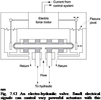 |
Early helicopters were beset by weight and stability problems where solving one often made the other worse. A further issue is that by definition there was not initially a pool of experienced pilots to fly the first helicopters and any extra stability would be very welcome.
The flybar was an appropriate and elegant solution at the time and played a pivotal role in the development of the helicopter, but subsequent developments have made it obsolete in the full size, although it is still found in most model helicopters.
Early helicopter blades were relatively lightly built because power was limited. This resulted in a rotor with low inertia having a high following rate in response to a cyclic control input or an external disturbance. Making the blades heavier would reduce the following rate, but the weight could not be accepted. The flybar essentially stabilizes the machine by reducing the rate at which the rotor can change its attitude. Although the flybar works, it raises the drag and complexity of the rotor head and causes a performance penalty. Later systems were developed which sensed the machine’s attitude using miniature gyroscopes. Correcting signals were then fed into the powered control system. In a sense the flybar was miniaturized and put in a black box.
Figure 7.43(a) shows how the Bell flybar system works. This was developed by Arthur Young, using initially electrically driven models. It was subsequently used on a number of full-sized machines including the Bell 47 and the Huey. Use is restricted to two-bladed rotors. The flybar is mounted across the rotor on a bearing parallel to the feathering
|
Fig. 7.43 (a) The Bell/Young flybar system. The flybar is essentially a gyroscope. (b) In this example the main rotor will stay parallel to the plane of the flybar because there is a unity relationship between the flybar attitude and the amount of cyclic pitch applied. |
axis of the blades. The control rods from the swashplate are attached to a pair of mixer arms pivoting in the flybar. Further rods from the mixer arms then operate the pitch control arms of the blades.
It will be seen from Figure 7.43(b) that if the swashplate remains fixed, with a suitable linkage the rotational axis of the flybar effectively can become the control axis of the rotor, because the blades tend to stay parallel to the flybar. This is called a unity mixing system. A smaller stabilizing effect is still obtained if the feathering of the blades is some proportion of the flybar motion.
The flybar is influenced by dampers on a bar fixed to the rotor shaft. If the flybar rotational axis and the shaft axis are different the dampers will oscillate because the flybar is effectively flapping with respect to the shaft. This action tries to bring the flybar axis parallel to the shaft axis at a rate proportional to the divergence between the axes.
If the flybar is tilted in any axis, the maximum flapping velocity is reached at 90° to that axis. As the dampers produce a couple proportional to velocity, this couple will be about an axis at 90° to the flapping axis. This couple will cause the flybar to precess into alignment with the rotor shaft. Thus the flybar is a gyro loosely tied to the rotor shaft. The flybar axis will align with the shaft axis when the machine is in equilibrium, but in any manoeuvre the divergence will be proportional to the rate of change of the attitude of the shaft axis, i. e. the roll rate or the pitch rate of the hull. Thus the angle of the flybar relative to the mast is a measure of the roll rate of the helicopter.
The flybar is gyroscopic so it will tend to hold a constant rotational axis. If, in steady flight or in the hover, the tip path plane of the rotor is disturbed by a gust, the tip path axis and the flybar axis diverge, which must result in cyclic feathering. This will counter the disturbance and restore the attitude of the disc. The resultant helicopter is very stable because the action of the flybar resists disturbances to the disc attitude.
The action of the flybar when the cyclic control is applied is also beneficial. The mixing levers also allow the flybar to oppose the cyclic input from the swashplate. If the swashplate is tilted to initiate a roll, the blades will cyclically be feathered through the mixing levers and the roll will commence. However, the flybar is measuring the roll rate, and the flybar axis will diverge from the shaft axis. In fact the flybar axis lags behind the shaft axis. This divergence applies an opposite feathering action to the swashplate.
For a given application of cyclic control, the blade cyclic feathering will be nulled for a given angle of divergence between the flybar axis and the mast axis. As this divergence is proportional to the roll rate of the helicopter, it follows that the roll rate actually achieved is proportional to the swashplate tilt. Thus the rotor system is turned into a rate control whose following rate is determined by the inertia of the flybar and the viscosity of the dampers. As the flybar axis can only roll slowly, the following rate of the rotor to the cyclic controls is reduced, giving the effect of a heavier rotor but without the actual mass.
The response of the rotor can be adjusted by changing the degree of damping. If the dampers are made more viscous, the following rate increases because the flybar is more powerfully tied to the shaft axis.
The action of the flybar can be analysed by treating it as a servo. Figure 7.44 shows that the swashplate supplies the desired roll rate, and the flybar measures the actual
|
Fig. 7.44 The Bell flybar acts like a servo, adjusting cyclic pitch to obtain the desired roll rate. If the flybar is tilted with respect to the mast, the dampers will gradually bring it back into alignment. The rate of response to the controls is proportional to the degree of damping. |
roll rate. The mixing levers subtract the actual roll rate from the desired roll rate to produce the roll rate error. This applies cyclic feathering in the sense that reduces the error. Thus the error is kept small such that the actual roll rate is equal to the desired roll rate.
The second major flybar development was due to Stanley Hiller and this was used in many of the early Hiller machines. The main difference between the Young and the Hiller systems is that in the Hiller the flybar has aerodynamic properties as well as gyroscopic properties and so is properly called a control rotor. Figure 7.45 shows that the control rotor is mounted transversely on a bearing as before, but there are two major contrasts with the Young system. First, the Hiller control rotor has full authority over the cyclic pitch of the main rotor, such that the control rotor axis completely determines the control axis of the main rotor. Second, the Hiller control rotor has small blades or paddles and it has feathering bearings. Pitch control arms on the control rotor lead to the swashplate so that cyclic pitch control of the control rotor is obtained. The pilot’s cyclic control actually flies the control rotor, whose attitude will then be followed by the main rotor.
The following rate of the control rotor can be made as slow as required by changing its Lock number, i. e. the relationship between the mass of the paddles and their lifting area. Thus as before, relatively light blades can be made to respond relatively slowly. The control rotor will not respond rapidly to gusts and so the attitude of the machine is stabilized as it is in the Young system.
The Hiller system has the advantage that the pilot only has to produce enough force to feather the control rotor. The control forces to feather the main rotor are created by lift on the paddles. Thus not only does the Hiller system provide following rate control
|
Fig. 7.45 In the Hiller system, the flybar is gyroscopic as in the Bell system, but damping is aerodynamic. The flybar also provides power assistance through the application of cyclic pitch to the paddles. |
and autostabilization, it also provides power-assisted cyclic control, with the penalty of an increase in drag due to the paddles.
The Hiller control system incorporates another unusual feature in that the swashplate works in reverse to that of a conventional helicopter. Figure 7.46(a) shows that in order to simplify the control runs, Hiller took an arm from the non-rotating part of the swashplate straight down to the pilot. The pilot would move the end of this arm in the same way as he would a conventional floor-mounted cyclic stick. In order, for example, to apply aft cyclic, the pilot would pull the end of the arm towards himself. This, however, had the effect of tipping the swashplate down at the front. Hiller solved this problem by connecting the rotating part of the swashplate to the control rotor with a scissors linkage that reverses the action.
Figure 7.46(b) shows that when the swashplate tilts forwards, the control axis of the control rotor tilts backwards as required. When the overhead control was replaced by a conventional floor-mounted cyclic in later machines, the reversing swashplate was retained and the cyclic pushrods were simply rigged to make the swashplate move in the correct sense.
It is interesting that many examples of the Bell 47 and the Hiller Raven are still flying, although the Bell 47 first flew in 1943 and the Hiller in 1948. The longevity of these designs is testimony to the original concept. The flybar was also adopted in the UH-1 Iroquois, better known as the ‘Huey’ which itself achieved legendary status.
The Bell and Hiller systems are ideal for two-bladed teetering rotors, but it is not easy to apply them to rotors with a larger number of blades. Irven Culver at Lockheed developed stabilizing systems to work with rotors having any number of blades. Culver had rightly concluded that flapping and dragging hinges were not necessary and set out to build hingeless rotors. Without flapping hinges, the cyclic response of a rotor can be extremely rapid and exert huge forces on the hull. Gyroscopic stabilization was essential to contain control response.
The Lockheed CL-475 was a flying test bed that sported a variety of rotors and stabilization systems. Initially a two-bladed rotor was used having no flapping hinges and no collective pitch control. Lift was controlled by rotor speed. Cyclic pitch was provided by a single span-wise hinge. A flybar was mounted transversely to the rotor. This superficially resembled a Bell flybar, but only because of the streamlining of the tip weights. The attitude of the flybar with respect to the mast controlled the cyclic pitch of the rotor and the pilot’s cyclic stick applied forces to the flybar via springs and the swashplate to make it precess. As the main rotor changed its attitude, pitch link loads would make the gyro bar follow, serving the same function as the dampers in the Bell system. A second gyro stabilized the yaw axis by controlling the tail rotor pitch.
In the Bell system some of the travel of the flybar is lost in the mechanical mixer needed to add in the cyclic control from the swashplate. The direct control of the main rotor by the gyro in the Lockheed system allowed greater loop gain and was thus more stable. However, the two-bladed hingeless rotor suffered from excessive 2P hop in forward flight and work concentrated on hingeless rotors with more than two blades.
In 1960 a new three-bladed rotor was designed, again having no flapping hinges. Initially, each blade had its own single-ended flybar known as a gyrobar. This is shown in Figure 7.47. In the gyrobar system, the feathering axis is not parallel to the blade, but instead the feathering axis is swept back with respect to the blade. As was shown in section 4.7, this causes coupling between the flapping and feathering axes. If the rotor
![]()
|
|
|
|
|
disc should tilt for any reason, the inter-axis coupling causes the feathering bearing to turn slightly, and a couple is applied to the gyrobar. If a given blade is imagined to rise, an upward couple will be applied to its gyrobar. The gyrobar will then precess by 90° causing the blade pitch to increase 90° after the stimulus. As the blade is also gyroscopic, the blade would respond by rising a further 90° after the stimulus. As a result the blade responds at 180° to the stimulus and is thus stable.
Cyclic control is obtained by applying couples to the gyrobar using the swashplate. The inertia of the gyrobar means that it will control the following rate of the main rotor.
In 1961 a ring gyro having direct control of blade cyclic pitch was fitted below the rotor. A collective pitch mechanism was also fitted so that constant RPM could be used. In this form the CL-475 was widely demonstrated and achieved a reputation for stability that represented the state of the art at the time. The machine still exists with the ring gyro and is at Fort Rucker at the time of writing.
Subsequently the Model 286 (XH-51) was developed. This hingeless machine initially had three blades, but changed to four blades again for vibration reasons. The ring gyro is replaced by a rigid four-legged flybar, again directly coupled to the cyclic pitch arms of the rotor blades such that the flybar axis forms the control axis of the main rotor. Gyroscopic rigidity of the flybar means that any unwanted disturbance of the main rotor attitude due to gusts is automatically opposed.
The Lockheed system achieves cyclic control by applying control couples to the flybar via the swashplate to make it precess in the required direction. The cyclic control system is unlike that of any other helicopter because it provides forces, not displacements. This is no more than a scaled-up version of the use of torque motors to erect gyroscopic instruments as was seen earlier in this chapter.
Figure 7.48 shows that couples are applied to the flybar by a system of springs. Each of the control runs, pitch and roll, contains a pair of springs, one positive and one negative. With the cyclic stick at neutral, the geometry is such that if the swashplate moves because the flybar has tilted, one spring is compressed and the other extends
To
swashplate
|
stick Fig. 7.48 In the Lockheed system the flybar is caused to precess by the application of couples. A double-spring arrangement allows the precession without interference from the other cyclic axis. See text. |
by a similar amount. The springs will balance each other over a significant range of movement of the flybar. Thus if the flybar tilts it will not experience a restoring force from the controls. However, if the controls are displaced from neutral, the spring imbalance is upset and the result is a couple applied to the flybar.
Control is achieved as follows. If the pilot wishes to roll the machine, this can only be done if the flybar is made to roll. As the flybar is gyroscopic, it can only be made to roll by applying a couple in the pitch axis. Consequently the controls are rigged such that the roll cyclic pushrod applies a pitch couple to the flybar through the spring system. The flybar will sense this couple and correctly precess with a 90° lag to perform the commanded roll. The flybar is allowed to precess in this way by the balanced springs in the pitch pushrod.
The hingeless model 286 was aerobatic and performed loops and rolls with ease, whilst remaining easy to fly. Essentially the same control approach was adopted in the first models of the Lockheed Cheyenne compound helicopter (see Chapter 9). The high speed of this machine increased the loads that the rotors fed into the gyro through the pitch links, undermining gyro authority. The solution was the system shown in Figure 7.49. Lockheed called this the AMCS (advanced mechanical control system). Here the gyro has been moved inboard, below the transmission. The absence of an external flybar reduces drag. The gyro is fitted with a swashplate through which it controls the mechanical inputs to hydraulic actuators. These provide an irreversible control over the cyclic pitch so that pitch link forces from the blades cannot reach the gyro. The hydraulic actuators operate a spider that passes through the centre of the gyro and the transmission and emerges above the rotor head where it operates pitch links.
The gyro is supplied with couples by the pilot’s cyclic control using the positive and negative balanced spring system as before. These are not shown in the diagram. Having eliminated pitch link loads with the hydraulic actuators, the gyro is now made to follow the hull attitude using springs attached to the mast.
Lockheed’s AMCS represented the ultimate mechanical helicopter gyrostabilizer, but even as it was being tested, systems were being developed using miniature gyros and electronic amplification and the future of helicopter stabilization would lie in that direction.
Flybars are still found in flying model helicopters. Models are harder to fly than the full size and the flybar allows a welcome degree of stability for the pilot who won’t have
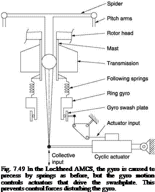 |
the same level of training as his full-size counterpart. Beginners often fit extra weights to the flybar to reduce the following rate even further. The flybar also allows the use of inexpensive and lightweight wooden blades whose following rate alone would be too fast.
The Bell system was difficult to replicate in miniature because of the hydraulic dampers, and the pure Hiller system was found to produce a very low following rate in models. As a result a hybrid system combining both and aptly called the Bell-Hiller system evolved. This uses the cyclic mixing of the Bell bar, as well as the Hiller paddles and control rotor feathering. There are thus three rods coming from the swashplate: one to each of the flybar mixer arms, and one to feather the control rotor. This arrangement gives a good balance between stability and response, although the number of links involved makes it look like a dog’s dinner. The falling cost of the piezo-electric gyroscope and its minute size mean that the flybar can now be eliminated in the model helicopter.
Autopilots vary in complexity, but the general goal is that the pilot is relieved of the need to maintain some parameter of the flight. In a helicopter it is possible to begin with stabilization of the roll axis only, and then add extra features. Automatic control of the tail rotor allows balanced turns and flight at minimum drag. Control of the pitch axis allows the airspeed to be held, and altitude can be held with collective control. Some systems can achieve a stable hover in a fixed location without pilot intervention.
Achieving any or all of this requires an intelligent combination of flight parameter sensing, error measurement, power-operated controls stabilization and ergonomics. In addition to these basics there are some additional criteria. In the same way that two pilots cannot simultaneously have control, it is not possible for a human pilot and an automatic system to have full authority over the helicopter at the same time.
In stability augmentation systems, also called AFCS (automatic flight control systems), pilot and AFCS share control so that the pilot actually flies the helicopter but the added inputs from the AFCS make the helicopter follow the pilot’s wishes more readily.
In simple autopilots there may be no control sharing at all and some mechanism needs to be provided so that the pilot can engage or disengage the autopilot so that one or other has full authority. These control reconfigurations must take place smoothly so that there is no sudden disturbance of the machine when the autopilot engages or disengages. Clearly safety is paramount and autopilots must use extensive interlocking so that they will not engage if correct conditions are not present and so that they will disengage and hand back control to the pilot in the case of a failure. In a simple system the servo output is physically disconnected from the controls when the pilot has control, but is connected by a clutch when the servo has control. Clearly the clutch is either engaged or disengaged and so this is not a control sharing arrangement and would not be appropriate for an AFCS.
An autopilot that maintains the machine on an absolutely stable course is in one sense ideal, but in practice the course or altitude needs to be changed from time to time. If the autopilot had to be disengaged and re-engaged every time a course change was required its value in reducing pilot workload would be diminished. Thus it is necessary to provide a means whereby the pilot can direct the flight through the autopilot. In fixed-wing practice this happens relatively infrequently and it is adequate to give the pilot an auxiliary set of control wheels or knobs which are used to direct the autopilot to new flight conditions without touching the main controls.
Figure 7.2 showed ways of dividing control between a servo and a pilot. Either a series or parallel arrangement can be used to share control between a small electric servo and the pilot on the mechanical input to a conventional hydraulic actuator. This approach is appropriate if the AFCS or autopilot are optional equipment because the same hydraulic actuator can be used with or without the servo. Where the autopilot is standard equipment, the electric servo can be dispensed with. Figure 7.50 shows a parallel-connected hydraulic actuator designed to allow full control authority by the pilot with the autopilot disengaged and full autopilot authority when engaged. Fluid flow to the main ram is controlled by one of two spool valves. One of these is mechanically operated by pushrod from, for example, the cyclic stick to give pilot authority. The other is operated by electro-hydraulic valve (EHV) to give autopilot authority. Note that the ram is grounded to the airframe and the body of the actuator moves.
Figure 7.50 shows that with the autopilot disengaged the EHV and its spool valve are isolated from the main ram by the autopilot select valve which is closed by spring pressure. If the pilot moves the input pushrod this will displace the manual spool valve and admit fluid to the ram so that the actuator moves bodily (‘follows up’) until the spool valve is in the neutral position again. In this mode the system is working as a conventional power-assisted actuator as was described in section 7.21.
Provided all of the interlock conditions are met, when the pilot engages the autopilot, the engage interlock output signal operates a solenoid valve admitting hydraulic pressure to a cylinder. This drives a tapering lock pin that moves the manual spool valve to the neutral position, locking it to the actuator body so that no relative movement is
|
interlock Fig. 7.50 With the autopilot disengaged, the pushrod from the pilot’s controls operates the spool valve upper right. With the autopilot engaged, the solenoid valve admits pressure to the engage piston which moves up, locking the pilot’s pushrod to the actuator and connecting the EHV outputs to the hydraulic ram. |
possible. The second opens the autopilot select valve connecting the EHV spool to the main ram.
Now the autopilot can move the control by supplying a signal to the EHV and can measure the control position using the feedback signal from the LVDT in the ram. Note that as the pilot’s controls are locked to the actuator body by the engage cylinder, they will move as the autopilot operates, giving the pilot confirmation that the machine is literally flying itself.
Two nested feedback loops are involved here. The outer loop consists of the attitude gyro to produce an error if the machine turns around the stabilized axis for any reason. The attitude error will compensate for factors such as the moment of inertia of the helicopter about the controlled axis and will then be fed to the actuator loop. The actuator loop converts the attitude error into a control movement in such a sense that the error is cancelled. The actuator feedback loop stabilizes the controls and gives the servo stiffness against flight loads. The machine will maintain the attitude dictated by the gyro indefinitely.
When the autopilot is engaged it has full authority. If the pilot tries to move the controls of a parallel system, the stiffness of the hydraulic actuator will oppose him. The LVDT will sense an unwanted movement and the autopilot will operate the EHV to oppose it. Instead the autopilot control panel carries knobs the pilot can turn to give the autopilot a new reference. Effectively the pilot’s control knob adds an offset to the output of the reference sensor. For example, if the pilot wished to make a constant rate turn, he would set the turn control knob to an appropriate angle. This would add an offset to the roll axis gyro output that the autopilot would sense as an attitude error. The autopilot would roll the helicopter until the attitude error was apparently cancelled. Thus only a 5° bank angle signal from the gyro would cancel a -5° bank input from the control knob. The helicopter would indefinitely remain at a bank angle of 5° and
|
Fig. 7.51 Autopilot interlock. The autopilot cannot be engaged unless all of the necessary conditions are present. |
make a constant rate turn. Note that a hazard could exist if the autopilot were to be engaged with the control knobs inadvertently set away from neutral. Accordingly the control knobs have centre detents that operate interlock switches so that engagement is impossible unless the control knobs are in a safe position.
Figure 7.51 shows an illustrative autopilot interlock. A number of conditions must be met before power can reach the engage relay. All necessary power must be present, flight directors must be off, the gyros must be erected and the control knobs must be neutral before the engage switch receives power. The engage switch is spring biased to return to the off position, but if all the interlock conditions are met it will be held in the engage position by a solenoid. When the engage switch is operated this feeds power to a relay which applies power to the solenoid, holding the switch in the engaged position. If the interlock conditions are not met the engage switch will return to the off position as soon as it is released.
The relay has further contacts which bypass the control knob centre switches so that these can subsequently be moved. Power is also fed to the autopilot solenoid in the actuator to enable the EHV. If while the autopilot is engaged any autopilot interlock condition fails, the holding current to the engage switch will be interrupted and the switch will spring back to the off position. The pilot may also disengage by pressing a button on the control column to break the holding current.
In the modern AFCS, the control knobs have been dispensed with. Instead the autopilot reference can be changed intuitively using the normal controls. When the autopilot is engaged, in a traditional system the manual controls are locked and any attempt to move them would be met by the rigidity of the actuator. However, if a force sensor is fitted in the control stick or in a pushrod it is possible to sense that the pilot is trying to move the stick. Figure 7.2 showed that the stick force signal can be used to modify the AFCS reference attitude so that the AFCS acts to implement the new attitude. In doing so, the AFCS moves the pilot’s stick. When all of the parameters are correctly set, the pilot’s stick moves by virtually the same amount for a given manoeuvre with or without the AFCS. Systems of this type are intuitive and much more appropriate for helicopters which are generally flown at lower altitude and in closer proximity to potential hazards. Such autopilots can be left engaged at all times. If the pilot wishes to perform an emergency manoeuvre, it is not necessary to disengage the autopilot; an instinctive movement of the controls is all that is needed. The autopilot acts as an AFCS and makes the machine execute the manoeuvre more accurately. However, if a small dead-band is incorporated in the stick transducer, the autopilot can sense when the pilot has released the stick and will then maintain the last attitude indefinitely.
An autopilot that can only maintain attitude is not enough. For prolonged use the ability to maintain airspeed and altitude is also required. For instrument landing the ability to maintain a specified rate of descent is essential, as is the ability to move smoothly from altitude control to descent control as the glide slope is entered.
An encoding altimeter as described in section 7.10 produces an actual altitude signal and this is subtracted from the desired altitude set on a dial by the pilot. The resulting altitude error will be cancelled by climbing or descending using the collective control. When cruising at a fixed altitude the necessary rates of climb and descent will be very small, but if the pilot directs the system to a new altitude, a significant rate of climb may result. In the absence of a stabilator, this will increase the downwash on the tail plane and give an aft trim effect. However the vertical axis gyro will sense this as an attitude error and try to cancel it with forward cyclic. This will produce undesirable mast bending and vibration. A solution is to feed a small proportion of the collective climb command across to the cyclic system to modify the pitch axis reference allowing a slightly tail down attitude for the duration of the climb.
The climb will also require more torque and although the yaw control of the autopilot would handle this a better result may be obtained if the measured torque is fed into the yaw system.
Airspeed is easily obtained from the dynamic pressure at the pitot head. In a sophisticated system, the static pressure may also be used to compensate the indicated airspeed (IAS) to true airspeed (TAS). The pilot enters the desired airspeed on a dial and a subtraction produces the airspeed error. An increase in airspeed requires the application of forward cyclic to tilt the thrust vector, an increase in collective pitch to maintain altitude, a change of lateral cyclic trim because of inflow and a change of tail rotor pitch because of the increased torque.
In a simple system the airspeed control might simply apply a forward pitch command to the vertical attitude reference. The resulting loss of height would then be sensed by the altitude hold system that would increase collective to maintain height. The increased torque would cause the yaw stabilizer to operate and the roll attitude would be held against inflow changes by the roll axis stabilization. However, all of these changes could take some time to stabilize. Instead of letting an error occur and then allowing the automatic system to cancel it, it is more accurate to anticipate the error by issuing an appropriate command. This is known as feedforward. For example, if the amount of tail rotor pitch needed to cancel torque is known for all combinations of power and airspeed, then if a power change is commanded, the appropriate pitch change can be added directly to the tail rotor. In this way the tail would not yaw at all during a power change unless the feedforward had not been correctly assessed. Part of the development phase of an autopilot system is to map the feedforward parameters over the entire flight envelope.
Feedforward of this kind may be used in manually controlled helicopters. For example, the collective lever position can usefully be linked to the tail rotor pitch. An increase in collective pitch will require more rotor drive torque and a corresponding increase in tail rotor pitch. By passing the tail rotor cables over a system of pulleys operated
by the collective lever, the amount of pedal input needed, for example when entering autorotation, is reduced.
Fast forward flight requires a combination of forward cyclic to oppose the advanc – ing/retreating lift difference and raised collective to handle increased inflow. In some helicopters, as the collective lever is raised a degree of forward cyclic may automatically be applied to reduce the amount of retrimming needed.
Once an autopilot is available which is sensitive to external direction, automatic navigation becomes possible. Using inertial sensing, radio navigation, Doppler or other means the course can be corrected automatically to bring the machine to a desired destination. This is known as coupling and a unit known as a flight director allows the pilot to select which control source is coupled to the autopilot.
 |
 |
 |
In the heading (HDG) position of the flight director, the yaw reference for the autopilot becomes the magnetic-compass-locked DI such that the helicopter will maintain a fixed magnetic heading. In the VOR position of the flight director, the yaw reference becomes the bearing of a VOR (VHF omni-range) beacon so that the machine can fly directly towards (or away from) the beacon. Figure 7.52 shows that a VOR beacon radiates in the VHF aircraft band and is modulated with two low frequency sinusoidal signals. One of these is radiated in the same way in all directions, whereas the relative phase of the other signal is a function of the direction of radiation. The in-phase condition is aligned with magnetic north and the phase lag is equal to the magnetic bearing on which the radiation leaves the beacon. The beacon also transmits its identifying signal in Morse code.
Fig. 7.52 In the VOR (VHF omni-range) system there are two transmitted signals. One of these is the same in all directions whereas the phase of the other is a function of direction. The receiver can determine the direction along which the transmitter was sending and the bearing of the transmitter must be the reciprocal of this.
Thus if a VOR receiver detected a 90° lag in the signals, this would indicate that the receiver lay on a bearing of 90° from the beacon. The beacon would then be at 270° with respect to the receiver. A cockpit indicator makes this reciprocal indication automatically. In order to fly along a selected radial, the pilot turns the omni-bearing selector knob on the display until the desired radial heading is at the top. If the autopilot is now coupled to the VOR receiver, should the track deviate from the required radial, a phase change will be picked up which will modify the roll reference of the autopilot until the correct radial is being flown. This will be indicated when the deviation pointer on the display points straight up to the selected radial heading. The display will also indicate whether flight is to or from the beacon.
The signals become erratic as the beacon gets very close. Consequently the VOR coupling is disabled automatically when this condition is sensed and the flight director uses magnetic heading to continue flight until the beacon is behind the machine when VOR coupling will resume with the ‘from’ indicator showing.
Figure 7.53 shows how an ILS (instrument landing system) works. There are four transmitters associated with each landing site. The localizer is sited at the far end of
|
|
|
|
|
selected here intercepted here Fig. 7 .53 An ILS installation. The localizer guides the aircraft horizontally onto a path which aligns with the runway. The glide slope beams make the altitude a suitable function of distance so the aircraft descends at the correct angle to the threshold. The markers tell the aircraft how far it is to touchdown. |
the runway and transmits a pair of beams that are equally off the axis of the correct approach path. These are sensed with equal strength when a correct approach is being made. The glide slope transmitter is sited at the approach end of the runway. This also radiates two beams, this time equally off axis with respect to the ideal glide slope. These two beams are sensed with equal strength on the correct glide slope. There are also two highly directional antennae radiating beams directly upwards into the approach path. These are the outer and inner markers.
In order to make an instrument approach the helicopter will initially be on autopilot flying with altitude hold. Once in the vicinity of the approach path, the ILS receiver is tuned to the correct frequency and once identified the autopilot will be coupled to the locator using the LOC position of the selector. The locator alone is not enough to ensure a correct approach and the desired heading of the autopilot needs to be set with the heading of the runway. In this mode the autopilot is influenced by both the localizer signal and the heading error.
As Figure 7.53 shows, the heading could be correct but the helicopter could be approaching parallel to the runway. In this case the heading error would be zero but the localizer error would be issuing a steer left command. The machine will steer left until the localizer error balances the heading error. As the approach path is acquired, the localizer error becomes smaller and so the balancing heading error also gets smaller. The result is that as the machine flies onto the localizer beam centreline it will adopt the correct heading with both errors zero.
The machine will then fly along the beam centre with altitude hold still on. At some point the receiver will intercept the glide slope beams. The point at which this occurs will depend on the altitude. When the glide slope beams are detected, the autopilot coupling must be set to GS (glide slope) mode. The horizontal coupling is unchanged, but the altitude hold is disabled and replaced with coupling from the glide slope receiver. The glide slope information will act on the autopilot by reducing the desired altitude if the machine is above the beam and increasing it if it is below. The result is that the helicopter descends down the glide slope. As the flight path is already aligned with the localizer beam, the helicopter must be on a direct course for the glide slope transmitter.
The markers indicate the progress of the approach. The outer marker is about four NM from the threshold and transmits continuous Morse dashes. The inner marker is about 3500 feet from threshold and transmits alternating dots and dashes.
Using the ILS transmitters the helicopter can make an automatic approach. A machine without an autopilot could make a manual instrument approach with the pilot using left/right and up/down indicators to fly down the glide slope. In the case of an autopilot failure the pilot could elect to continue the approach manually in this way.
At some point the so-called decision altitude is reached. In the case of a manual instrument approach or an automatic approach with a single channel autopilot, if the landing site is not visible by the time the decision altitude is reached, the landing must be aborted. Only a suitably equipped machine may carry on to make a blind landing. Such a machine must carry a triply redundant voting autopilot, a RADAR altimeter and Doppler RADAR to measure groundspeed. A pressure altimeter is simply not accurate enough. At a RADAR height of a few hundred feet, the constant glide slope and airspeed are both modified to produce a flare. The disc attitude is pitched back to slow the machine down and collective is lowered to prevent zooming.
As RADAR height falls, forward speed control is switched from dynamic pressure to Doppler RADAR so the groundspeed can be brought to zero a little before RADAR altitude reaches zero. This gives time for the hull to level before touchdown which will be programmed to be within the landing gear limit.
In feedback systems an error is amplified to operate a control. In normal operation this makes the error smaller. However, if there is a failure the error does not get smaller. In the case of an attitude stabilizer controlled by vertical gyro, if the roll attitude signal from the gyro failed and went to an arbitrary value, this would result in a massive roll error which would apply full roll control in an attempt to correct it. This is known as a hardover and is an unfortunate failure characteristic of all feedback systems. In practice equipment has to be designed to prevent hardover failures compromising safety. In a simple approach the authority of the automatic pilot is limited so that it cannot apply full control. Slipping clutches may be present in the controls so that the pilot can overcome the incorrect forces and regain control. In more sophisticated systems extensive monitoring is carried out. If a signal deviates from the range of levels in which it normally operates, the signal may be clamped to a null value to prevent a hardover and the autopilot will be disengaged.
In military helicopters natural parts failure is not the only problem. The designer has to consider that the helicopter may come under fire and will take steps to allow control to be retained despite a reasonable amount of damage. In practice this means retaining control after hits from rounds of up to half-inch calibre.
The first line of defence is redundancy. Duplicated hydraulic systems are essential, but it is important to run the pipes far apart so that a single round cannot rupture both systems. The location of twin engines spaced widely apart in the Apache is another example of this philosophy. Mechanical control signalling is vulnerable to small arms fire as a single round can sever a pushrod. It is much harder to disable a multiply redundant digital signalling system which takes different routes through the airframe and where the processing power is distributed in small units all over the airframe. In fact some attack helicopters use the mechanical signalling only as a failsafe in case the fly-by-wire fails. Where control paths cannot be separated, as for example near the pilot’s controls, the armour plating which protects the pilot will also be employed to protect critical parts of the control system.
Redundant hydraulic actuators have the additional problem that the failed actuator may be jammed due to impact distortion or a round lodged in the mechanism. In this case the remaining actuator will be unable to move the jammed control. The solution is to construct actuators with frangible pistons. In the event of an actuator seizure, the working actuator can develop enough thrust to break the jammed piston free of the actuator rod.
Where hydraulics are concerned, it is clear when a failure has occurred, and so it is equally clear which actuator should retain authority. However, in electrical signalling systems a failure in a signal processor could result in an entirely spurious voltage or digital code being output. This could have any value over the whole control range. If there are only two control systems it is impossible to know which is giving the right answer. The solution here is triplication where there are three separate systems comparing the actual position with the desired position. In this case a single failure will result in one actuator drive signal being different from the other two. A comparison or majority voting system can determine which signal is out of step and disable it.
As with the hydraulics, electrical power sources must be duplicated. Critical electrically powered devices may be fed by multiple sources using blocking diodes. A voting signal processor can take power from the battery wiring or from both generators. If any power source fails its voltage will fall and the diode will reverse bias and block any power drain so that power is still available with any one source still functioning.
There is a good parallel here with the use of one-way clutches and multiple engines. The one-way clutch is a mechanical diode.
There can be more than one voting unit in a real system. The pilot’s joystick may be fitted with multiple encoders and a voting system to determine if one has failed. The LVDTs on the hydraulic actuator may have the same system so that reliable feedback signals are available. The outputs of the multiple signal processors will also be subject to voting. In this way the probability of control loss due to natural parts failure is rendered infinitesimal and real protection against battle damage is provided.
When redundancy, electronic processing, automatic stability, flight direction and powered controls are combined, remarkable systems can be realized. It is not inconceivable that future attack helicopters would have the ability to fly themselves home in the event that the crew are disabled.
8


