Correlation of Flapping with Test Results
 |
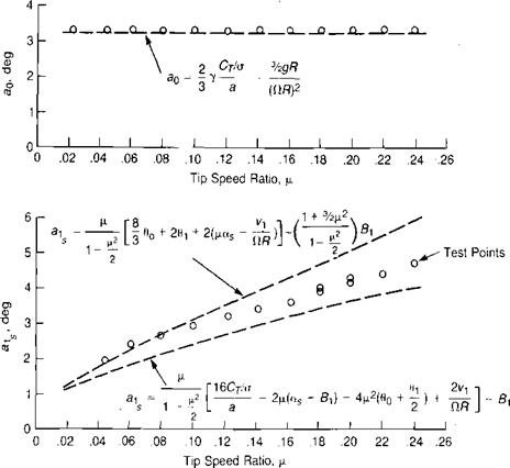
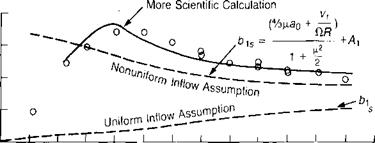
Reference 3.5 presents flapping obtained during a wind tunnel test of a model rotor at low tip speed ratios. The measured values of coning, longitudinal flapping, and lateral flapping are shown in Figure 3.34 along with values calculated from the
![]()
![]()
![]()
 + Ал
+ Ал
Tip Speed Ratio, |i
FIGURE 3.34 Measured and Calculated Flapping for Wind Tunnel Model
Sources: Harris, “Articulated Rotor Blade Flapping Motion at Low Advance Ratio,” JAHS 17-1, 1972; Johnson, “Comparison of Calculated and Measured Helicopter Rotor Lateral Flapping Angles,” AVRADCOM TR 80-A-11 NASA TM 81213, 1980.
equations derived here. Two calculated lines are shown for longitudinal flapping. The first is based on the equation derived earlier and the second on an alternative form generated by combining the equations for ax and CT/o:
![]()
![]() 6CT/o
6CT/o
1–ЄІ L
2
This second equation gives lower calculated flapping because the wind tunnel model produced a somewhat lower value of Cx/a than would be predicted from the test conditions. (This correlation of longitudinal flapping is slightly different from that given in reference 3.5 because of a term equivalent to 4|i2(90 + jdx) was omitted from that study.)
The presence of the term vJClR in the lateral flapping equation is the result of assuming that the induced velocity distribution is nonuniform—specifically, that it has the form:
V, =VA 1 + К———————- COS 1/ )
* /
where К is assumed to equal to unity. The assumption is obviously not valid near hover, as shown in Figure 3.34, but above a tip speed ratio of about 0.05 it gives better correlation than the calculations based on uniform inflow. More detailed analysis of the role of the induced velocity distribution will be found in references 3.5 and 3-6. The large lateral flapping at low forward speeds requires left cyclic stick to trim the helicopter (for rotors turning counterclockwise). (Pilots refer to this as the "transverse flow” effect.) The magnitude of this cross-coupling effect is shown by the lateral flapping equation to be a function of vu which in turn is a function of the disc loading. In sideward flight, forward stick must be held in flight to the right and aft stick in flight to the left. This effect is discussed in reference 3.18.
A much more scientific approach can be used—one involving a free wake analysis—as is reported in reference 3.19. This results in an almost perfect correlation with the wind tunnel data for lateral flapping.


