Engine-off landing tests
The aim of engine-off landing tests varies depending on the role of the aircraft. In the case of helicopters without a training role the aim is usually to prove that a safe landing is possible and to offer some advice in the aircrew manual. For aircraft with a training role where EOLs are likely to be commonplace a much more comprehensive series of tests is needed. The aim of these tests is usually to establish a box defined in terms of the airspeed and height at which the initial flare should be started. Within the box the handling qualities will be such that a student pilot can perform an EOL without undue skill; clearly the larger the box the more suitable the helicopter will be for teaching the skills required for engine-off landings.
The tests commence using the speed for minimum ROD in autorotation and a flare height determined from the powered recovery tests. Although the co-pilot makes a call at a pre-determined height on the radar altimeter, the responsibility for choosing when and how to perform the manoeuvre always rests with the handling pilot. The next point is then flown keeping the airspeed the same but changing the flare height. For each combination of speed and height the pilot rates the difficulty of the manoeuvre taking into account such things as predictability of the touchdown point, rotor speed control, proximity of the tail to the surface, touchdown speed and control margins. A series of these tests then allows construction of the box. At no stage is a point attempted that has a combination of an untried flare height and untried airspeed. Wind velocity, aircraft AUM and density altitude all affect the manoeuvre and therefore the power-off landings programme starts with the most favourable conditions and then moves incrementally to the least favourable.
7.6.4.4 Avoid area testing
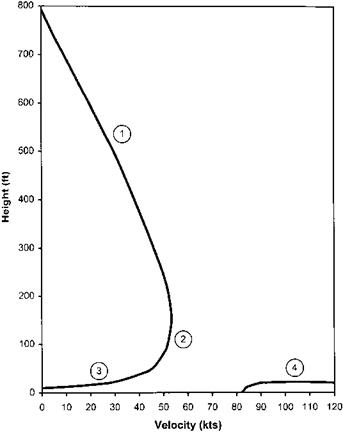
The final stage of a power-off assessment programme is to define the avoid curve, avoid area or height/velocity diagram. An example of the type of presentation commonly seen in aircrew manuals is shown in Fig. 7.13. An avoid area diagram shows the operational pilot the combinations of airspeed and height above the surface from which a total loss of power is unlikely to be survivable. Armed with this information the pilot can plan the aircraft’s flight path to minimize the time spent at risk inside the area. A number of assumptions are normally made in the construction of height/ velocity diagrams:
• The aircraft is in level flight or the hover at the moment of power loss.
• There is a total intervention delay time of 2 seconds.
• There is no wind and the surface is suitable for a landing.
It is common practice to present different charts for sea level and a higher density altitude (in the region of 5000 feet); similarly several charts can be produced to account for variations in aircraft AUM.
The height/velocity diagram can be divided into four areas indicated as 1 to 4 on Fig. 7.13. Area 1 is dictated by the height loss required to achieve an autorotative
|
Fig. 7.13 Typical height/velocity diagram. |
state and to accelerate the aircraft to an airspeed where an effective flare can be made. In Area 2 around the knee of the curve, the aircraft will not develop steady autorotation nor will a significant increase in airspeed be possible. Here the pilot will only be able to level the pitch attitude and use the remaining energy in the rotor to cushion the landing. Area 3 is dictated by the energy-absorbing qualities of the undercarriage and the rotor inertia. Area 4 needs to be avoided to allow sufficient height for the pilot to perform a flare to reduce groundspeed.
Performing avoid area testing carries with it a high level of risk which is mitigated by using test pilots who are fully familiar with the power-off landing characteristics of the aircraft being tested. Of course the standard risk reduction method of approaching each test point incrementally is applied rigorously in these trials. Testing starts from a known and benign point, for example, 500 ft and 60 KIAS; the height is then kept constant and the speed reduced by a small amount (5 to 10 kts) and another failure is simulated. After each landing the pilot awards a difficulty rating or an HQR. This process is repeated using small reductions in airspeed until the test pilot judges that the difficulty of performing the landing is such that following a sudden engine failure an operational pilot would not be able to achieve a survivable touchdown. For the testing of the low height points in Areas 3 and 4 the airspeed is kept constant and the height is incrementally increased or decreased as appropriate. It is a strict rule that only one parameter is varied between one test point and the next; these parameters include airspeed, height, wind velocity and direction, density altitude, AUM, aircraft configuration, intervention time and finally the individual test pilot.


