Entries into autorotation with delay times
A vital part of the test programme is to determine the delay time (intervention time) that is possible between an engine failure occurring and the pilot lowering the collective. As explained earlier the intervention time is made up from the rotorcraft response time and the pilot reaction time. The pilot reaction time to be applied is usually specified by the procuring authority but traditionally a total intervention time of two seconds has been used for helicopters suffering a total power failure in level flight. This may be thought of as a 0.5 s rotorcraft response time and an attentive hands-on pilot response time. Thus it should be possible for the pilot to move the controls up to two seconds after the engine failure has occurred without the rotor speed reducing below the minimum permitted value at any stage during the recovery. This type of testing is clearly high risk and is normally monitored using telemetry.
The following terms are used to enumerate the rotor decay (see Fig. 2.26 for a graphical representation):
NR0 = rotor speed at which power loss occurs
|
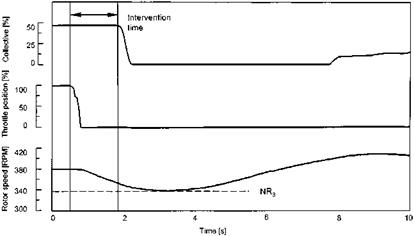
Fig. 7.12 Lever delay test data. |
NR1 = rotor speed when pilot commences recovery action by lowering the collective NR2 = rotor speed when collective lowered fully NR3 = minimum NR achieved
NR4 = a nominal value related to the normal autorotative rotor speed (once NR has increased to this value it is assumed that the entry phase of the autorotation has been completed)
Tests start with a simultaneous ‘throttle chop’ and lever lowering from VMP in level or descending flight. The minimum rotor speed achieved is noted and from this the total rotor speed drop is calculated (NR0 — NR3). A delay time is then introduced by allowing the rotor speed to fall to a pre-determined value (NR1) before the collective is lowered, as shown in Fig. 7.12.
The *Nr is calculated again (*NR = NR1 — NR3) before a new NR1 is selected for the next point. This process is repeated using incremental reductions in NR1 until the minimum permitted rotor speed is achieved on the underswing, a handling difficulty is experienced, or the specified intervention time is met. As discussed in Section 2.12 the values of NR1 and NR3 are plotted to allow the trend to be monitored and thus the minimum rotor speed to be predicted for the next test point. It is important to note that a valid trend will only be established if a consistent technique is used every time; for example, yaw on engine failure is corrected immediately, the same rate of collective lever lowering is used and the airspeed is adjusted only after NR4 is reached. A check is made on the consistency of each lever lowering by noting and comparing the minimum value of normal acceleration achieved.
After the initial tests have been completed at VMP the airspeed is varied to determine the effect that this has on the intervention delay time. At higher speeds the aircraft is flared as the collective is lowered to reduce the rotor speed loss. At lower airspeeds the aircraft is accelerated to the minimum rate of descent airspeed once rotor speed has recovered. In all cases information is gathered to assist the test team in conducting avoid area tests subsequently. Thus the height loss involved in regaining the nominal autorotative rotor speed (NR4) and minimum RoD airspeed is noted. For the highspeed cases the height loss during the intervention time and the height gain possible during the flare are needed. On a full test programme of new rotorcraft further tests may be required to explore the effects of density altitude, AUM and initial power setting.


