Helicopter performance
Helicopter performance may be assessed in a large number of areas and as these interact to a considerable extent it is difficult to categorize. As helicopters are expensive to operate in comparison with aeroplanes, economic performance is important. Factors such as the fuel consumed, parts worn out and maintenance needed determine the operating cost that is generally calculated on an hourly basis. Operating cost will be assessed by commercial users in proportion to payload. Clearly such economy will only be realized if the machine is fully loaded. Operators will consider machines that offer a payload close to their typical requirement in order to avoid the poor economics of flying partly loaded. In the case of privately owned machines, the payload may be little more than the pilot and passengers, but here different economics apply as the cost of flying may be offset against time saved. In the case of military operators, economics may not be the overriding concern.
Operational performance may be taken to include factors such as the range, airspeed and altitude that can be obtained with various payloads. As the advantage of the helicopter is its ability to hover, the greatest altitude that can be reached in forward flight is somewhat academic and less important that the altitudes at which the machine can hover in and out of ground effect at various weights. Hover out of ground effect (HOGE) altitude is the highest altitude at which the machine can take off vertically, and will be lower than the hover in ground effect (HIGE) altitude. This is the highest altitude at which the machine can get into the hover, which would allow a running take-off if a sufficiently unobstructed area is available. These altitudes, and many other performance factors, are functions of air temperature. If valid comparisons are to be made, test results must be presented in a way that eliminates atmospheric variables. The necessary techniques will be discussed shortly.
Tactical performance may include the manoeuvrability of the machine. Many aspects of this are determined by the load factor, although the power of the tail rotor controls the yawing ability and the ability to hover in crosswinds. Associated factors are the range of positions the CM may take and the weight of underslung load that can be lifted. Military and coastguard users find these aspects of performance more important than commercial users. Achieving high load factor and high tail rotor power may raise weight and operating costs that a commercial operator cannot tolerate. In some cases there are variants of a basic machine each of which is optimized for a particular market. There will be exceptions in the case of specialist operators. Helicopters designed
for underslung delivery of stores by the military may be well suited to logging or construction of ski lifts.
Performance and safety are closely related. Operating an aircraft outside its designed performance envelope may result in excessive stresses that can cause damage or even failure. Consequently during the development of a machine, extensive tests are needed to establish just what these limits are. These limits are published in the flight manual in order that pilots are aware of them. A helicopter’s performance can be measured in terms of factors that contribute to safety. The degree of stability may affect pilot workload and compromise safety on long flights in poor conditions. If it is intended to operate a helicopter in IFR, the stability performance may have to be improved by passive or active means. Performance is important not just under normal conditions, but also under abnormal conditions. Autorotation performance becomes important in the case of power loss. In twin-engine machines the performance with one engine inoperative (OEI) is crucial if the safety benefit of two engines is to be more than an illusion. The ability of a helicopter to continue flight under icing conditions is also a performance factor.
The atmosphere is the medium in which helicopters fly but it is also one of the fuels for the engine and the occupants breathe it. It is a highly variable medium that is constantly being forced out of equilibrium by heat from the sun and in which the pressure, temperature, and humidity can vary with height and with time and in which winds blow in complex time – and height-variant patterns. The effect of atmospheric conditions on flight is so significant that no pilot can obtain qualifications without demonstrating a working knowledge of these effects.
The atmosphere is a mixture of gases. About 78% is nitrogen: a relatively unreactive element whereas about 21% is oxygen which is highly reactive. The remainder is a mixture of water in the gaseous state and various other traces. The reactive nature of oxygen is both good and bad. The good part is that it provides a source of energy for life and helicopters alike because hydrocarbons can react with oxygen to release energy. The bad part is that many materials will react with oxygen when we would rather they didn’t. Chemically, combustion and corrosion are one and the same thing. The difference is based on the human reaction to the chemical reaction.
Gases form the highest energy state of matter in which the molecules are no longer bound together strongly as in solids or weakly as in liquids but instead are free to rush around at a high speed that is a function of absolute temperature. The countless collisions between gas molecules and any non-gaseous object result in pressure at the interface. Pressure is measured by physicists and by engineers in units of force per unit of area using imperial units of pounds per square inch or SI units of Newtons per square metre. At sea level, the atmosphere exerts a pressure of about 15 pounds per square inch and has a density of about 0.075 pounds/0.002378 slugs per cubic foot, or in metric units about 100 000 Newtons per square metre with a density of 1.225 kg per cubic metre. Over the years, many other units of pressure have evolved, some from meteorology. One of these is the bar (after barometry) where one bar is the average atmospheric pressure at the place where the bar was defined. In practical use, the bar is divided into 1000 millibars. The bar is slowly being replaced by a numerically identical unit known as the hectoPascal (hPa). The bar and hPa are commonly used in aviation altimetry. The principle of the mercury barometer is that atmospheric pressure supports a column of mercury exposed to a vacuum at the top. Consequently the length of the
column is proportional to pressure and can be expressed in inches or cm of mercury. At sea level a reading of about 26 inches of mercury is obtained. This unit may be found in use in altimeters originating in the United States.
The gas law states that the product of pressure and volume is proportional to temperature. Reducing the volume means that external work has to be done to oppose the pressure. This work increases the temperature of the gas. The Diesel engine obtains ignition in this way. Conversely if the volume is increased, work is done by the gas and the temperature must fall. This is why carburettors are prone to icing on part throttle because the air expands on entering the manifold. Air conditioners work in the same way.
If the volume is fixed, as temperature rises, the velocity of the molecules increases and so the impact at each collision with the walls of any container is greater and the pressure rises. Alternatively the same pressure can be exerted in a given volume with a smaller mass of gas. Thus in the atmosphere where pressure increases can be released by free movement, the result of an increase in air temperature is that the density goes down. Density is also affected by humidity. Water molecules are heavier than those of atmospheric gases and increase the pressure due to molecular collisions. Thus in the presence of water vapour a given pressure can be sustained with a smaller mass of air and the density goes down.
In order for meaningful comparisons to be made between various test results, it is important to eliminate variations due to atmospheric conditions. The International Standard Atmosphere (ISA) is a defined set of fixed conditions, somewhere within the spread of conditions found in practice. When a test is made, the actual atmospheric conditions are measured. Using the laws of physics, it is possible to calculate the effect of every difference between the actual conditions and ISA. If all results are corrected in this way, they can be presented with respect to ISA and as a result can immediately be compared with any other results obtained in the same way. Similarly, if the performance of a machine is defined in the flight manual with respect to ISA, it is possible to correct for the actual conditions and predict the real performance that can be expected.
In the ISA, pressure and temperature at mean sea level (MSL) are defined, along with standardized rates at which these change with height. Relative humidity (RH) is also defined to be zero. ISA MSL pressure is 1013.2 hPa. Temperature is 15°C and the density is 1.225 kg/m3. The ISA lapse rate defines temperature as falling at 1.98°C per 1000 feet (which is a mongrel unit being part metric and part imperial). Although the height of the tropopause is a function of latitude because the earth is rotating, ISA defines the tropopause as 36 000 feet and above this the air temperature is -56.5°C. For many purposes the approximation of -2°C per 1000 feet can be used as the lapse rate.
Given the above, the pressure and density of the ISA can be calculated for any height above sea level. The density is important because it directly affects the power that can be produced by the engine(s) and the thrust produced by the rotors.
Altimeters do not measure height because they are basically pressure gauges with a creative scale. Only in ISA conditions does an altimeter measure height because the pressure will correctly match the scale reading. In all other conditions, the altimeter reads altitude, best defined as estimated height subject to an error. If sea level pressure at
the location in question is known, the error can be minimized by adjusting the altimeter setting scale to that pressure. However, if instead the altimeter setting scale is set to the ISA MSL pressure of 1013.2 hPa, the altimeter reads pressure altitude. This is defined as the altitude in the ISA at which the same pressure exists. Pressure altitude is used primarily for flight in airways where it assures vertical separation (see section 7.7).
Whereas pressure is primarily a navigational tool, density is what governs performance. Engines produce power by releasing thermal energy due to combustion of hydrocarbon fuel in air. The mass of fuel that can be burned is directly proportional to the mass of the air available, whereas physical limitations in the construction of the engine set the greatest volume of air that can be drawn in. Consequently the density has a significant effect because it determines the mass of air per unit of volume the engine has drawn in. Lift is obtained when the rotor imparts downward momentum to the air. As the disc area is fixed, the volume of air the rotor can influence is also fixed for a given flight regime. Thus the degree to which the rotor can impart momentum is controlled by air density.
In the ISA the density at a given height will always be the same because ISA defines MSL pressure and temperature and specifies zero humidity. Thus using the standard figures, the pressure and temperature at any height can be deduced and the density must follow from that. In practice, the pressure and temperature will differ from ISA and the local density will not be ISA density. The concept of density altitude was introduced to allow for such changes. Density altitude is the altitude in the ISA at which the density is the same as the present density. In order to assess the performance of a machine under real conditions, the pilot will calculate the density altitude for those conditions and then consult the flight manual where the performance is specified as a function of density altitude.
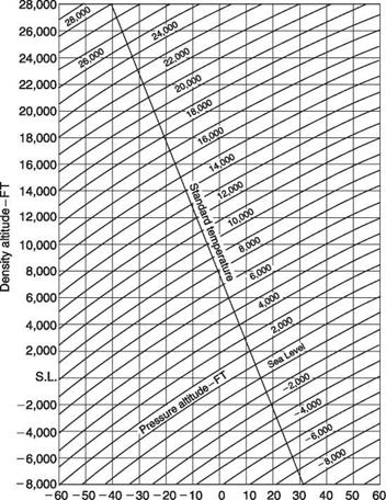
Figure 8.1 shows a standard density/altitude chart that converts pressure altitude entered on the diagonal lines to density altitude measured along the vertical axis. The horizontal axis is air temperature and the single line falling to the right shows the ISA air temperature falling with height at the standard lapse rate with pressure altitude. Thus the chart shows that the line corresponding to zero pressure altitude crosses the line corresponding to zero density altitude at 15°C (ISA MSL conditions). In order to use the chart, the local pressure altitude is located where it crosses the ISA lapse rate line. Reading vertically down from this pressure altitude will give the ISA temperature for that height. If the actual temperature is the same, the pressure altitude and density altitude are the same. However, in practice a different temperature will often be found. If the diagonal line sloping from bottom left to top right and corresponding to the pressure altitude is followed until it intersects a vertical line drawn up from the actual temperature, the vertical position of the intersection determines the density altitude. The figure shows an example. In some flight manuals, the conversion to density altitude may be incorporated in certain performance charts. An example will be given in the next section.
The effect of humidity is not generally considered in density altitude charts, but a rule of thumb used by pilots is to add 1000 feet to the density altitude if the humidity is high. Typically helicopters have no means to measure humidity and the pilot’s estimate has to be used.
Helicopter operation is largely concerned with power management. The power plant supplies power and the airframe demands power. Both supply and demand are
|
Temperature -°С Fig. 8.1 A density/altitude chart. This allows density altitude to be obtained from pressure altitude. The chart corrects for ISA standard lapse rate and allows compensation for non-ISA temperature. See text. |
subject to considerable variations. Sustained flight is not possible where demand exceeds available power. In the opposite case, flight in equilibrium is possible with a power surplus, usually called a power margin, which can be used for climbing or for manoeuvres.
In general the engine(s) provide power which has a physical limit to the transmission which has a physical torque limit. For a constant RPM machine such as a helicopter rotor, power is proportional to torque and engines may be described in terms of torque available. The engine power/torque available will be a function of density altitude. The rate at which fuel can be burned is limited primarily by the temperature that the power turbine blades can withstand. At low altitude, the compressor can produce plenty of mass flow and the combustion takes place with excess air that limits the power turbine temperature. As altitude increases the air density falls and the mass flow reduces. At some point the amount of fuel burned must be reduced to prevent excessive turbine
temperature. From then on available power must fall. However, the fall in power is not as steep as might be expected because intake air temperature falls with altitude and this offsets the loss of density due to reduced pressure to some extent. As a result the engine power/torque available curve may show the characteristic knee of Figure 8.2. At low density altitudes the torque must be kept within the constant transmission limit whereas above a certain density altitude the available torque falls.
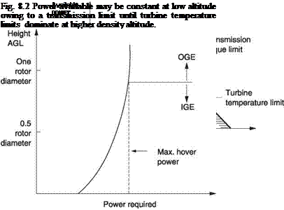 |
The rotors in turn require power that is a complex function of density altitude and airspeed. The power will be delivered to the main and tail rotors and will be absorbed by various forms of drag. Power required to hover is clearly important and the worst case will be at zero airspeed. Figure 8.3 shows a typical chart relating hover power
Fig. 8.3 Simple hover power chart.
to skid height for fixed density altitude. Above about one rotor diameter the power becomes constant and the machine is considered to be out of ground effect (OGE). In the flight manual, a chart similar to that shown in Figure 8.4 may be given. This allows hover performance to be predicted for any combination of all-up weight (AUW)
![]() HOVER
HOVER
100% ROTOR RPM
CALM WIND
LEVEL SURFACE
Fig. 8.4 Complex hover power chart allowing for AUW, density altitude and temperature. (Boeing)
and density altitude. The top right section of the chart allows density altitude to be computed by finding a point where a horizontal line from pressure altitude on the left scale intersects the free air temperature line. A vertical line from this point will give a reading on the density altitude scale. This line will also intersect the AUW curve on the bottom right chart. Moving left from this point will give a reading on the hover OGE torque scale.
The bottom left chart converts the hover OGE torque to the torque needed at various skid/wheel heights. The HOGE line is at an angle of 45° and does not change the torque required. However, the lines for various heights of IGE have different slopes and reduce the torque accordingly.
The chart can be used in different ways. In the above example the pressure altitude, air temperature and AUW were used to find the torque needed to hover. However, from AUW and known altitude of the destination it is possible to deduce the maximum air temperature at which a vertical landing could be made. In the case of an engine failure, the chart can also be used to show that above a certain AUW hovering even in ground effect is impossible and a rolling landing on a runway would be needed.
In practice, power needed to hover is affected by windspeed. In most cases the power needed will be reduced, except if the wind is from a particular direction and at a particular speed that causes the main and tail rotors to rob one another of inflow. This phenomenon was considered in Chapter 5. The tandem rotor helicopter is less sensitive to wind direction in the hover.
Turning next to forward flight, Figure 8.5(a) shows how the various power requirements typically change with airspeed. The rotors will require induced power and profile power and the hull will require parasitic power to overcome drag. The induced power will be high in the hover and falls as airspeed increases. This is because forward flight gives the rotor access to a larger mass of air per unit time and production of thrust becomes more efficient. The induced power will also increase with AUW Profile power will also rise with AUW and increases slightly with airspeed as the profile drag on the advancing blade increases more than the drag on the retreating blade lessens. In contrast, the parasite power is substantially independent of AUW, but increases with airspeed. The drag force will increase as the square of airspeed, but the power is the product of the drag force and the airspeed and so will increase as the cube of the airspeed. At very high speeds the rotor disc must be inclined forwards substantially so that the horizontal component of thrust from the rotor can become large to overcome hull drag. This nose-down attitude may make the hull drag even greater. As main rotor thrust increases the tail rotor thrust will also need to increase to counteract torque and so the tail power will also increase at high speeds.
Figure 8.5(b) shows that there is an airspeed, typically around 50 knots, at which the total power is minimum. At this airspeed the induced power has fallen but the parasite power has not yet risen seriously. The figure also shows the available power, which is relatively constant, although in some machines it rises with airspeed owing to the ram effect of dynamic pressure at the intake. The power required reaches the available power on the right and this would determine the highest airspeed that could be reached, assuming no structural limits or retreating blade stall effects. At all lower airspeeds, a power margin exists and so the machine can take off vertically. At the minimum power airspeed the machine can stay airborne for the longest time. Clearly the greatest power margin exists at this airspeed and thus the maximum rate of climb would be obtained at full power. The minimum rate of descent in autorotation will also be obtained at this airspeed.
Figure 8.5(b) contrasts the conditions for a normally loaded machine at sea level, with the conditions for a high AUW, where the available power only exceeds the required
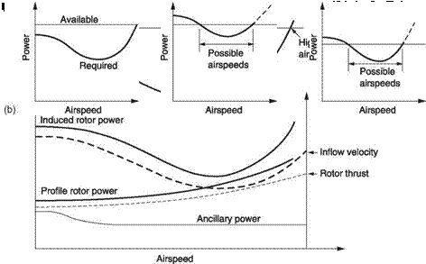 |
Fig. 8.5 Power as a function of airspeed. At (a) the various contributions from different sources have different functions of airspeed. At (b) flight is only possible where available power exceeds required power. With high AUW the power needed exceeds that available over part of the speed range. High density altitude reduces the power available and also limits the speed range.
power over a range of airspeeds and the conditions for a high density altitude where the available power has fallen. Once more level flight is only possible over a range of airspeeds.
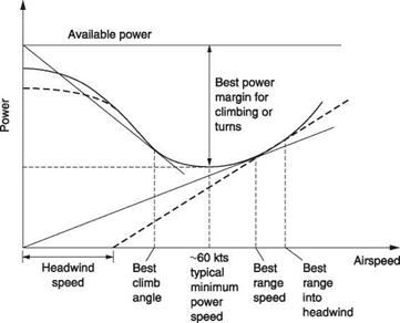
The airspeed that will yield the greatest range is not obvious. The problem can be approached by considering that greater distance can be flown at higher speed, provided it does not require disproportionately more power. The key here is the proportionality. If an increase in airspeed of, say, 5% needs a power increase of 4%, then obviously it is worth going faster, whereas if a speed increase of 5% requires a power increase of 6% the range will fall. Consequently an approximation to the best range in still air is
|
Fig. 8.6 Maximum range speed. In still air this is found by a line from the origin tangent to the power curve. In the case of wind the origin is offset by the windspeed. |
obtained by finding the airspeed at which the rate of power increase is exactly equal to the rate of airspeed increase. Figure 8.6 shows that this speed can be found graphically where a line from the origin is tangential to the power curve. The presence of wind changes the situation. In this case it is necessary to find the airspeed at which the rate of power increase is exactly the same as the rate of groundspeed increase. Figure 8.6 shows that this can be found graphically by offsetting the origin by an amount given by the component of wind velocity in the direction of flight. For a headwind, the maximum range speed will be faster than that needed for still air.
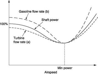
There is a further complication in practice, because a real engine does not consume fuel proportionally to power produced. This is particularly true of turbine engines that sustain a loss of efficiency due to driving the compressor. This loss becomes a smaller proportion of total power as power produced increases and so it is a characteristic of a turbine that efficiency increases with power. Consequently the best range speed according to Figure 8.6 is not strictly correct for a turbine helicopter. To be precise, the machine should be flown at the airspeed where the rate of fuel consumption increase is exactly the same as the rate of groundspeed increase. Figure 8.7 shows fuel consumption against power normalized at minimum power speed. At (a) is the curve for a turbine helicopter. This has the same trend as the power curve that is also shown, but does not rise as steeply above minimum power speed because the engine is being used more efficiently. It will be seen that the airspeed for the best range is somewhat higher than the figure obtained in Figure 8.6. In practice the power curve, or the fuel consumption curve, remains close to the line from the origin over a range of airspeeds so it is not necessary to be rigid about the airspeed as the loss of range due to a moderate departure from the ideal is not serious. In practice the actual airspeed can usefully be faster than the theoretical maximum range speed by an amount that increases fuel flow by 1%. This gives a useful reduction in journey time with a negligible range penalty.
|
Fig. 8.7 Fuel flow for a turbine helicopter (a) and gasoline powered helicopter (b) superimposed on power required. Note these are not the same as the efficiencies of the two types of engine change differently with load. The turbine is inefficient at low power and most efficient at full power. The piston engine is most efficient at less than full power. |
Gasoline-engine helicopters behave differently. At high power, the mixture may have to be rich so that some additional cooling is provided by fuel evaporation and this reduces efficiency. In cruise, the mixture can be leaned out to make the engine more efficient and improve range. Thus a gasoline engine may be most efficient at some fraction of full power rather than at full power as is the case for the turbine. As a result the fuel consumption curve rises more steeply than the power curve away from minimum power speed as shown in Figure 8.7(b). Thus the spread of speeds for maximum range with a piston engine will be smaller than for a turbine. The gasoline engine does not run on excess air and so available power will fall off rapidly with altitude. However, if a turbocharger is fitted, engine power can be maintained at altitudes sufficient to reduce parasite drag.
Where the utmost range is to be achieved, flying at an appropriate altitude may be useful. There are two related factors to consider. The first is that all real helicopters need an available load factor significantly above unity so they can manoeuvre safely. The greatest efficiency is obtained by running the rotor blades at a CL of around 0.5, suggesting that the available ISA MSL load factor of a typical helicopter will be around 2. By definition cruise takes place at unity load factor where the lift to drag ratio changes little with CL. The second is that helicopters need engines whose power is appropriate for the load factor and in cruise these will be running inefficiently at part power. For the best range anything that reduces the load factor and improves engine efficiency should be considered. Reducing the air density may do both. In the case of a rotor running at constant RRPM, reduced air density will mean that a greater angle of attack is needed. However, if this changes CL from 0.5 to 0.6, the increases in induced drag and profile drag will be minor. However, there is a significant reduction in parasite drag.
A turbine engine has no actual throttle and so operates with excess air, like a Diesel engine. Unlike a Diesel engine, the compressor suffers profile drag. An efficient way of throttling a turbine engine back to cruise power is to reduce the density of the inlet air.
In a gasoline engine there is a throttle that forcibly limits the mass flow through the engine and reduces the inlet manifold pressure. The reduced manifold pressure opposes the motion of the piston on the induction stroke and causes pumping loss. Pumping loss can be reduced by supplying air with lower density and opening the throttle to compensate. Consequently flying at an appropriate altitude reduces the total power needed and makes both gasoline and turbine engines more efficient. In a gasoline engine there is another option available to increase efficiency, which is to use heated induction air. This is normally provided to prevent icing in humid conditions, but hot air is less dense than cold air and so throttles the engine back to cruise power with less pumping loss thereby increasing efficiency and range.
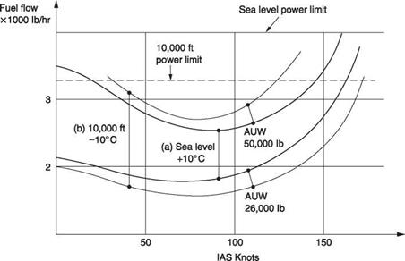
Figure 8.8(a) shows the fuel flow curves for a CH-47D at two AUWs at sea level and +10°C. Figure 8.8(b) shows the corresponding curves for the same AUWs but at 10 000 feet pressure altitude and the air temperature 20°C lower to allow for the lapse rate. It will be clear that the fuel flow is significantly reduced for the lower AUW by climbing to the higher altitude as the reduction in parasite power exceeds the increase in profile and induced power. For the higher AUW, CL becomes too large and the increase in induced and profile power outweighs the reduction of parasite power and fuel flow is higher.
If altitude is taken to extremes, it would depend on the design of the machine and the AUW whether the engine ran out of power before the rotor stalls or vice versa. In practice a somewhat lower altitude can be found at which a significant improvement in range can be had. On a long ferry flight with auxiliary tanks, the weight of the machine reduces significantly as fuel burns off and the optimum altitude will increase. The best range will be obtained by adhering to a calculated altitude profile throughout the flight. It should be noted that at very high altitudes, reduced air density results in reduced cyclic authority.
|
Fig. 8.8 Fuel flows curves for a CH-47D for two different AUWs. (a) At sea level. (b) At 10 000 feet (courtesy Boeing). |
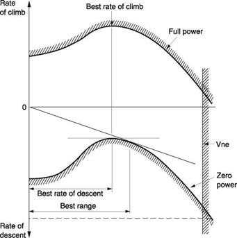
At airspeeds above 30 knots or so, the parasite power and the profile power and induced power of the rotors are affected only slightly by a change of disc inclination due to climb or descent. Hull drag will change slightly. Consequently it is reasonable to assume that any power margin in Figure 8.5 is available for climbing. Figure 8.9 shows a graph of power margin against airspeed. Effectively the upper curve is the difference between available power and power needed at constant altitude as a function of airspeed. By subtracting the available power from this curve, a lower, zero-power curve is obtained. The curves must terminate on the right at Vne and as a result the region in which flight is possible is bounded by the two curves. The upper curve shows the rate of climb available if the entire power margin is converted into potential energy. The lower curve shows the rates of descent possible in autorotation.
Figure 8.9 shows the best rate of descent without power is at the same speed as the best rate of climb with power. However, in the case of power loss the goal is to reach a safe landing area rather than to descend at the minimum rate. There will be more possibilities if the machine is autorotated at the airspeed that gives maximum range. That airspeed is also derived in Figure 8.9. As before, the origin needs to be offset for head or tail winds. In autorotation the power comes from the release of potential energy as the machine descends. In theory, the heavier the machine, the more power is liberated, so it should be able to fly further. Under certain circumstances this will be observed. Where an emergency dictates maximum range in autorotation, the pilot
|
Fig. 8.9 Power margin diagram shows performance envelope at full and zero power. |
 |
can increase rotor efficiency by reducing RRPM. This will reduce profile drag and require a larger angle of attack so that the lift to drag ratio will improve. Whilst very low RRPM is dangerous because it may not be possible to recover, a reduction of 10% is quite safe and has a dramatic effect on autorotation range. Prior to landing RRPM can be recovered by gradual application of back cyclic. In some machines the use of low RRPM may result in increased vibration if the rotor detuning has been optimized for a narrow RRPM range.
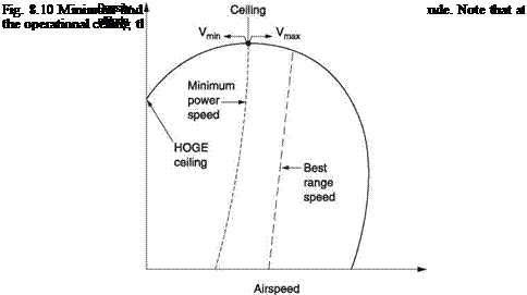
Figure 8.9 applies at one density altitude only and obviously climb or descent will change that. Figure 8.10 shows an alternative way of depicting the performance. This is a chart of minimum and maximum airspeed as a function of density altitude. Minimum power and maximum range speeds may also be shown as a function of density altitude. At sea level minimum airspeed is zero showing that vertical climb is possible. At some density altitude the HOGE power will exceed available power and then the minimum speed becomes non-zero. At sea level the maximum airspeed is power limited but may peak at some density altitude where reduced air density is reducing profile drag and improving rotor L/D. At higher density altitude maximum airspeed will fall again. As density altitude increases, the available power falls down into the power-required curve and the differences between minimum power speed, minimum airspeed and maximum airspeed become smaller. Where these speeds coincide, the absolute ceiling has been reached. As the absolute ceiling can only be reached asymptotically, the service ceiling is often taken to be a slightly lower density altitude at which a rate of climb of 100 fpm remains.
Given the existence of a minimum airspeed, potentially a helicopter could take off vertically at sea level with a full load and fly to some high altitude destination at best rate of climb speed where an attempted vertical landing would result in a crash. The fact that this does not happen in practice is due to a combination of the availability of power curves in the flight manual and piloting techniques that establish what the power margin is before attempting a landing.
In the case of a light piston-engine helicopter, the payload is small and the altitude performance modest. The flight manual may be quite sparse in the power curve department and safety is primarily assured by piloting technique. In the case of a heavy military transport helicopter, the payload may exceed the empty weight of the machine and flight in a wide combination of AUWs and density altitudes is possible. The flight manual may contain many pages of fuel flow curves for various AUWs, pressure altitudes and air temperatures. In the case of the CH-47D there are over 100 such curves.
When plenty of power is available, the steepest climb will be vertical. However, under certain combinations of payload and density altitude, vertical climb may not be possible. In this case obstacle clearance becomes an issue and finding the airspeed at which the steepest climb can be obtained is important. Even if there is a power margin, knowing the speed at which the steepest climb occurs is useful. The climb gradient is the ratio of climb speed to forward airspeed. Finding the optimum airspeed requires finding a point on the power curve where the surplus power is proportional to airspeed. Figure 8.6 shows that this can be done graphically by finding the point on the power curve where a line from the available power at zero airspeed is tangent.
In most cases the steepest climb performance will be required for obstacle clearance on take-off where there is insufficient power margin for HOGE. In this case the correct procedure is to make a running take-off by accelerating as hard as possible in ground effect and making no attempt to gain height until the best climb gradient airspeed is obtained. At this airspeed the attitude of the machine is adjusted so that no further increase in airspeed occurs. The machine will then climb at constant airspeed so that power margin goes entirely towards climbing. The flight manual may contain charts that allow obstacle clearance ability to be predicted for various AUWs and density altitudes.
It is not generally the case that multiple engines are fitted to obtain more power. Turboshaft engines are available with phenomenal power output and a single engine could lift any but the most extreme helicopter. Instead the goal of multiple engines is to provide some degree of resilience to engine failure. In the case of passenger carrying civil helicopters, multiple engines and suitable operational procedures together allow safe flight to be maintained in the case of a single engine failure at any time. In such cases a landing would be made as soon as practicable after the failure. In military machines, engine failure may result from hostile acts and has to be considered more probable than natural failure. Frequently it will be a goal that the mission shall be completed despite the loss of one engine. A prompt landing is not viable if the machine is over enemy territory or water and flight may have to be sustained.
Turbine engines are light in weight for the power they produce, so there is no technical difficulty in providing further engines, although this will reflect in purchase and running costs. If the remaining engine(s) is to be able to provide enough power for flight should one fail, then clearly under normal conditions all engines will be operating at a fraction of their maximum power and will be relatively inefficient because of the profile drag in the compressors. Turbine engines are very reliable and failures are relatively uncommon. Consequently instead of providing excessive continuous power, it is more sensible to design engines that can be overrated for short periods of time. The continuous power
rating of an engine is based largely on the temperature and rotational forces the blades at the hot end can withstand between overhauls. The oil-and air-cooling system will be designed to cope with these conditions. If these conditions are exceeded, the blade life will be reduced as higher than normal temperatures would increase the rate at which the blades creep or extend. The oil temperature may also rise. However, such conditions can be tolerated for a short time and an engine can be given a higher ‘contingency’ rating which it could only reliably tolerate for a few minutes. There may also be an even higher emergency rating that might only be sustainable for half a minute. If an engine failure is experienced during a critical phase of flight, the remaining engine would exceed its normal operating limits by entering contingency power to make up a good deal of the power lost.
If an engine enters one of these conditions, an indicator that can only be reset on the ground operates and a timer runs to measure the degree of overload. The use of these contingency power ratings in some cases may put the engine under such stress that it will need immediate and substantial parts replacement, particularly in the area of the blades at the hot end, but the frequency with which this happens is so low that the saving in fuel when the engines are working normally is of more consequence.
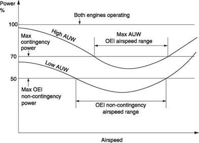
As machines have multiple engines for safety, it should be clear that adequate power should be available with one engine failed. With all engines running, more power is available than is needed. In this case the machine is flown normally by remaining within the transmission torque limits, whereas in the case of an engine failure the machine is flown within the ratings of the remaining engines. Figure 8.11 shows the example of a twin-engine machine in which the remaining engine will provide 140%
|
Fig. 8.11 One engine inoperative (OEI) conditions. If the remaining engine can provide 70% of transmission limit, with low AUW, nearly all of the flight envelope is available at contingency power, and a useful cruise envelope is available at non-contingency, or 50% of transmission limit. Such a machine could fly a long way after a failure. At high AUW, the machine can only stay airborne using contingency power, so it has to land before the time limit expires. |
of its continuous torque rating during contingency. This means that the helicopter has 70% of its usual torque available to deal with the failure and for landing. In the case of a heavily loaded helicopter, 70% of torque may not be enough under some conditions and as a result the helicopter will have a form of avoid curve with one engine inoperative within which it cannot maintain height. This condition can be dealt with by appropriate piloting. Pilots of twin-engine machines prefer to stay out of the OEI avoid region so that an unexpected engine failure can be dealt with readily.
Elementary safety considerations suggest that the operation of aircraft must be subject to regulations and procedures many of which are ultimately part of the law of the land. The flight manual forms part of that framework as in most countries it is a legal requirement to carry the flight manual in the aircraft to which it relates. All qualified pilots are aware of the general procedures and regulations regarding aviation, but the flight manual lists those facts specific to a certain model of aircraft.
Neglecting prototypes and experimental machines, aircraft in general operation must be certified. This means that, independently of the designer and manufacturer, the relevant authorities have examined the design of the machine and carried out flight tests. The examination is intended to ensure that all relevant regulations regarding the construction have been met and that as far as reasonably possible any areas of weakness or mechanical unreliability have been eliminated. The flight tests are intended to show that the aircraft has no handling peculiarities that might be beyond the skill of the average pilot and to establish the limitations of flight conditions. The compilation of the flight manual and the accuracy of its contents will thus be seen to be part of the certification process.
Part of the flight manual is known as the approved section. This part contains the information that is mandatory for safe operation. It will contain a table of contents and a mechanism for logging the incorporation of any subsequent updated or amended sections so that it can readily be established that the manual is complete and up to date. The approved section contains four basic types of information: limitations, normal procedures, emergency procedures and performance data.
Limitations set out in the flight manual are intended to prevent the machine being flown in inappropriate circumstances, or, when it is flown, to prevent it being subject to excessive stresses. Many helicopters are not certified for flight in icing conditions. Many are not certified for IFR. Some can only safely be operated with a pilot and a co-pilot. Few are certified for aerobatics.
Vne (airspeed not to be exceeded) primarily protects the blades and will often be specified as a function of altitude. The torque limit primarily protects the transmission. Turbine temperature limits protect the engine. The AUW of the machine must not exceed the figure in the flight manual. All-up weight can remain the same if the relative proportions of fuel and payload are changed. The distribution of weight is very important in a helicopter having a single main rotor. If the CM is some distance from the rotor shaft, cyclic control authority may be diminished in some directions and large alternating stresses are set up in the rotor. Figure 8.12(a) shows that the CM must be maintained within a conical region surrounding the shaft axis. In the case of a teetering rotor head, the apex of the cone coincides with the teetering bearing. In rotor heads with inbuilt flapping stiffness, the apex of the cone (b) will be above the rotor. Figure 8.12(c) shows that in a tandem rotor helicopter the fore-and-aft CM position must lie between two vertical limit lines. However, the position of these lines is a function of AUW
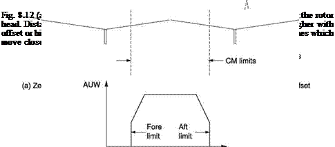 |
When lightly loaded, the CM of a tandem is subject to remarkable freedom, but as AUW approaches the maximum value the CM position is more constrained to prevent an excessive load being carried by one rotor. Note that a tandem rotor helicopter will also have lateral CM position limits and heavy payloads must be positioned on the hull centreline. In general the certification authorities are not concerned with how the position of the CM is to be calculated, only where it is. The manufacturer’s data will usually contain details on how the CM position is established.
In helicopters having zero-offset rotor heads, further limitations may be applied. The carrying of loads attached to the skids may be prohibited. There may also be a section describing the consequences of low-g or pushover manoeuvres designed to avoid mast bumping or boom strikes that are a characteristic hazard with this class of machine.
A windspeed limit for rotor starting may be found. Above that limit, blade sailing may be excessive, leading to droop stop pounding, blade damage or boom strikes.
In addition to the approved section, the flight manual will also contain a section provided by the manufacturer to assist in the operation of the helicopter. Civil flight manuals tend to be relatively sparse because aviation manufacturers have become targets for litigation in recent years. In contrast military flight manuals can be exceedingly comprehensive, particularly in areas such as fuel flow with respect to AUW and density altitude so that the best performance can be obtained from the machine.
An unconditionally stable aircraft is one that, if disturbed from trimmed flight, can be placed in any attitude and then, if the controls are released, it will return to straight and level flight on its own. The ability to return to straight and level flight is known as static stability, whereas dynamic stability is concerned with the manner, or promptness, with which the return occurs. Free flying model aeroplanes and some full-size aeroplanes are unconditionally stable. In forward flight on the upward part of the power curve, many helicopters are stable because the tail rotor acts like a fin and the tail surfaces have sufficient pitch authority. However, as the goal of the helicopter is to hover, a great deal of flying will take place on the back of the power curve where stability is impossible to achieve without pilot intervention or some artificial mechanism. Thus to be fair, it is not that helicopters are fundamentally less stable than aeroplanes, more that helicopters can explore flight regimes that are not available to aeroplanes in which control is simply harder.
Stability is a topic where there may be conflict between performance and safety and between complexity and economy. It is important to consider the entire system in order to form a balanced view. The airframe itself will have certain stability behaviour, but this will be modified by the actions of the pilot. Technically a helicopter airframe may be unstable, but piloting these unstable devices gives many of us a great deal of pleasure. This is because the actions of the pilot turn the unstable airframe into a stable system. In fact the unstable airframe with an intelligent pilot and/or control system forms the most manoeuvrable combination because it is axiomatic that the more stable the airframe is made, the less willing it is to deviate from its course.
Pilots very quickly become instinctive and fly at constant altitude with correct RRPM and no slip without conscious thought. It doesn’t make much difference to the pilot if the machine deviates from his intended course because of a gust or because it is has a degree of instability. The result is the same; he operates the controls to bring it back on course. In good conditions, the pilot has so little difficulty in doing this that he can fly a machine with significant stability problems without necessarily realizing. However, if visibility becomes poor so that the horizon is obscured, the pilot’s instinctive ability to stabilize the machine is impaired. Now the machine that is fun to fly VFR because it is so manoeuvrable becomes a menace in IFR because the workload involved in interpreting the artificial horizon and other instruments to make constant course corrections may be too great.
Today most helicopters are designed on the assumption that they will be used in IFR, but this has not always been the case. In practice machines certified for VFR only may have subsequently undergone a number of modifications in order to obtain IFR certification. These modifications frequently involve stability and pilot workload. In some cases modifications to stability can mean that a machine formerly requiring two pilots for IFR can then be certified for single pilot IFR flight.
The stability of the airframe can also be augmented artificially. Several of these techniques were shown in Chapter 7. In principle an unstable airframe with an artificial stability system gives the best of both worlds because the pilot can retain the manoeuvrability of the unstable airframe whilst enjoying the artificial stability. In practice some thought has to be given to what will happen if the artificial stability system fails in IFR. Either the artificial system has to be made redundant so that it continues to function in the presence of a failure or the airframe has to be made sufficiently stable that pilot workload remains reasonable if the augmentation system fails. Aerodynamic stability improvements are very reliable because they usually
involve the addition of passive structures or changes to the shape of the existing structure.
Stability in helicopters is a complex issue in comparison to aeroplanes because helicopters are more asymmetrical, have more coupling between their degrees of freedom and greater structural elasticity owing to the use of hinges and/or flexible blades. The inherent flexibility between the rotor and the hull is responsible for many peculiarities of helicopter behaviour. In many cases the rotor tries to do one thing and the hull tries to do the opposite and it is unclear which one will dominate. It also follows from this that the stability characteristics of helicopters having zero-offset rotor heads will differ from those having real or effective offset.
In all aircraft, stability can be subdivided into specific areas. Speed stability is the ability of an aircraft to return to trimmed airspeed after a disturbance. Pitch stability is the ability to return to the correct pitch attitude after a disturbance. Directional stability is the ability to keep the nose at the front and lateral stability is the ability to return the wings/rotor to a level attitude after a disturbance. If all of these are acceptable the machine may still have a problem due to the interaction of the lateral and directional stability mechanisms. This is known as spiral stability. Helicopters may further be assessed by their stability in the hover.
Speed stability of a main rotor is extremely good owing to the phenomenon of flap- back described in Chapter 3. If forward speed increases for any reason, the asymmetry of lift between the advancing and retreating blades results in a rolling couple which the main rotor will precess into rearward pitch. This tilts back the rotor thrust vector tending to reduce the airspeed. Thus the rotor itself has good speed stability. However, the hull is suspended below the rotor and the hull drag effectively acts at some distance below the rotor head, causing a downward pitching moment on the hull. Thus an increase in airspeed causes the hull to pitch down. Depending on the type of rotor head, this downward pitching moment will result in different hull attitude changes. As the swashplate is controlled from the hull, hull pitchdown will cause the rotor to pitch down.
Thus the helicopter itself may not display speed stability if the effect of the hull dominates the effect of the rotor. In practice the helicopter may need a tail plane to provide speed stability. If set at a suitable negative angle of incidence, the tail plane produces a downthrust that increases with airspeed and compensates for the hull drag.
In practice the rotor on its own has excess speed stability and large amounts of forward cyclic would be needed to increase speed. Thus some of the pitchdown due to hull drag can be used beneficially to reduce the cyclic travel needed. The tail plane area and incidence can be selected in such a way that the speed stability is just on the positive side of neutral. This means that airspeed increases will always result in the cyclic stick being trimmed forwards.
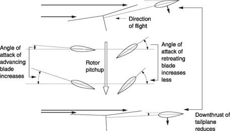
If the helicopter is disturbed on its pitch axis in forward flight, the RAF seen by the blades will change, but the advancing and retreating blades will see different changes. If a nose-up pitch disturbance is experienced, Figure 8.13 shows that the angle of attack of both blades will increase, but the increase seen by the advancing blade is greater. This produces a rolling couple to the retreating side that is precessed into a further nose-up pitching moment by the gyroscopic action of the rotor. Thus it will be seen that a rotor in forward flight is unstable in pitch. This is a further reason for the use of a tail plane in the helicopter. Dynamic stability here can be good because the tail plane has aerodynamic damping.
With a zero-offset rotor head, any tilt of the rotor disc in pitch is opposed because no couples are passed across the head and the hull and the swashplate attitude are little changed. If the rotor disc pitches but the swashplate doesn’t there will be an application
|
Fig. 8.13 The origin of pitchup instability. See text. |
of cyclic pitch opposing the pitching. In the case of a hingeless rotor head, couples can be passed across the rotor head and these can cause the hull to follow the rotor. Thus a helicopter with a hingeless rotor head will tend to be less stable in pitch. We expect that because such rotor heads offer greater manoeuvrability.
Helicopters with a conventional tail rotor have good directional stability. As was seen in Chapter 5, the tail rotor acts like a fin and has good yaw damping.
In aeroplanes, lateral stability is obtained by the use of dihedral or sweepback. If the aeroplane is rolled by a disturbance, it will slip in the direction of the roll and the relative airflow will have a sideways component. In the case of dihedral, the wing on the low side will see an increased angle of attack whereas the other wing will see a reduced angle of attack resulting in a righting couple. In the case of sweepback, the aspect ratio of the wing on the low side will improve and that of the other wing will worsen, achieving the same result.
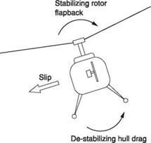
The mechanism in the helicopter is quite different. To find out what happens it is necessary to consider all moments acting about the roll axis which passes through the CM. In fact moments may be analysed about any axis, including one passing through the rotor head as Figure 8.14 shows. Essentially if a helicopter is disturbed in its roll axis it will slip and the main rotor will see a lateral component of airspeed. This results in sideflap that tends to oppose the roll and return the helicopter to a level attitude. Thus the rotor alone acts as if it had dihedral. However, the hull is suspended below the rotor and the displaced CM acts like a pendulum to create a righting moment. In addition, the lateral component of airspeed will cause a side thrust that tilts the hull in the same direction as the roll. Figure 8.14 shows that although the rotor is laterally stable, the hull is aerodynamically unstable. The outcome depends upon the vertical position of the CM, the aerodynamics of the hull and on the type of rotor head, but in most cases the stability of the rotor dominates and helicopters tend to be highly stable, possibly too stable, in roll. Dynamic stability is good because the rotor attitude has aerodynamic damping. The zero-offset rotor head is the least stable because there
|
Fig. 8.14 Lateral stability. In the rotor alone, lateral stability is automatic due to flapback, but the hull is unstable laterally because side slip tilts it further in the direction of roll. |
|
Side thrust of tail rotor and fin due
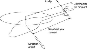
Fig. 8.15 Forces acting on a helicopter that has been disturbed in roll and which is slipping. The ratio of yaw to roll moments determines the spiral dive or Dutch roll characteristics. |
is no couple from the rotor to stop the hull being rolled by lateral drag. This has the effect of rolling the swashplate. This applies cyclic in a destabilizing sense. The hingeless rotor is the most stable because lateral drag cannot roll the hull so readily against the stiffness of the head. Thus lateral stability is better with the hingeless rotor: precisely the opposite of the case for longitudinal stability.
Figure 8.15 shows that in a helicopter with slip, the sideways component of airspeed will act on the hull, the tail rotor and on any fins. The fin and tail rotor are intended to create a yawing moment that turns the machine to face the direction towards which it is slipping. However, if the fin and tail rotor have a large area and are mounted low on the machine, the rolling moment they produce may exceed the stabilizing rolling moment from the main rotor. The helicopter may enter a spiral dive if disturbed in roll. Spiral instability may be remedied by lowering the CM, reducing fin area or by moving it upwards or forwards or by adding side area to the hull high up ahead of the mast. Upward relocation of the tail rotor and/or increasing the main rotor flapping offset will also be beneficial.
On the other hand if the fin and tail rotor are high mounted, they may hardly oppose the dihedral effect of the main rotor at all and the helicopter may have too much lateral stability such that if disturbed it suffers a phenomenon called a dutch roll.
Dutch roll describes a flight path like a corkscrew. Following a slip, excessive lateral stability creates a restoring roll couple so powerful that there is insufficient momentum for the helicopter to overshoot the correct attitude. The helicopter then oscillates about its path near-sinusoidally in pitch, roll and yaw but with phase differences between the motions. The motion may be damped heavily, so that it dies out or it may stabilize with certain amplitude. In some cases the amplitude will grow indefinitely. In most cases pilot intervention prevents such a divergence. However, for IFR operation, Dutch roll is considered as detrimental as spiral instability. Dutch roll may be remedied by raising the CM, by lowering the tail rotor, by reducing the main rotor flapping offset, by increasing fin area, by moving the fin back and/or down or by adding side area to the hull low down. Fences may be seen on the bottom of the hull for this purpose.
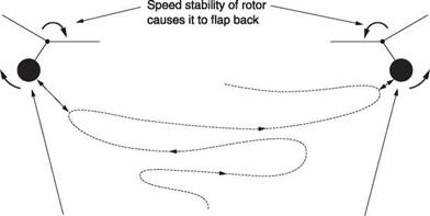
Hover stability is marginal in most helicopters because the hull mass is located below the rotor. It might be thought that this would act like a pendulum and give stability but this is not what happens. The hull has mass and is more or less flexibly suspended from the rotor according to the type of rotor head. As a result the attitude of the hull will always lag the attitude of the rotor. Figure 8.16 shows that if a helicopter is trimmed to stationary hover and then the controls are locked, it will begin a divergent oscillation. The rotor on its own is stable in the hover because if it moves in any horizontal direction, flapback will tend to arrest the motion. However, it can be seen from the figure that the hull swings from side to side under the rotor, but because the swashplate is referenced to the hull, that swinging causes cyclic inputs. These are not phased to damp the motion, but in fact augment the motion.
|
Momentum of hull hanging below rotor causes It to swing outward as rotor slows down due to flap back Fig. 8.16 Helicopters are unstable in hover and, without pilot intervention, will wander to and fro as shown here. |
|
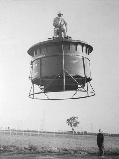
Fig. 8.17 The two Hiller VZ-IEs of 1957 were prototypes of the proposed Hiller Ring-Wing Coleopter, a craft capable of high-speed horizontal flight. (Hiller Museum) |
Hover stability can be obtained by putting the hull above the rotor. This causes enormous practical difficulties and it is usually better to accept the hover instability. However, Stanley Hiller designed a number of one-man helicopters (Figure 8.17) in which the pilot was above the shrouded rotor assembly and these were very stable. A machine built by DeLackner had the same attributes.
9


