Miss distance comparison
The other important factor for the pilot is the knowledge whether the missile annihilated the target. For our study miss distance serves as criterion, although the damage to a particular aircraft depends also on the missile’s warhead and fuse. We assume, somewhat arbitrarily, that a 6-m miss is the cutoff point for a hit. Any larger value constitutes a miss.
The simplifications of the five-DoF model, affecting miss distance, are in aerodynamics, autopilot, and, above all, in the seeker implementation. We replaced the detailed seeker code of the six DoF with an ideal seeker not constrained by gimbals and tracker loop. Multiple runs throughout the LAR-3 envelope with the five-DoF simulation lead, as expected, to hits everywhere. However, if we use the detailed six-DoF simulation with noise-corrupted seeker and sensor models, the envelope changes significantly.
To calculate the LAR-3 envelope for missiles with noise, multiple runs are made against every aimpoint. The miss distances are averaged and displayed as representative terminal miss performance. We use 30 such Monte Carlo runs against each aimpoint, employing the automated SWEEP methodology of CADAC for analysis and plotting.
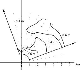
Figure 11.10 displays the results of an engagement at 5000 m altitude with both aircraft executing 7.5-g maneuvers at 0.75 Mach.
|
|
|
|

|
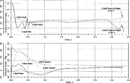
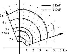
Fig. 11.9 LAR-3 time-of-ffight comparison. |
Compared to the five-DoF model, which delivers hits everywhere, the envelope is reduced for close-in shots (no hits within 2 km) and at high off-boresight shots beyond 5.5 km. The sweet spot lies at midranges and small look angles. A major reduction in real envelope performance occurs for look angles greater than 70 deg at all launch ranges. It is caused by the seeker gimbal limits. To understand this phenomenon, we need to look at the trajectory more closely.
The maximum look angle of the SRAAM seeker is 90 deg. This allows lock – on before launch throughout the envelope. After launch there is a delay of 0.25 s before guidance is enabled. During this time, the missile tends to align itself with its velocity vector by virtue of its inherent stability. This leads to a horizontal turning away from the target, through an angle perhaps as large as the launch angle of attack and a corresponding increase in seeker pitch-gimbal deflection. Whenever the seeker is locked on before launch at a gimbal angle between 90 and 90-a deg
|
Fig. 11.10 Six-DoF LAR-3 envelope; 30 Monte Carlo runs against each aimpoint. |
(a is the angle of attack of the shooter at missile launch), there is a chance that the weathercock stability of the missile will drive the gimbals to their stops. The reduced off-axis performance is shown in Fig. 11.10. Maximum gimbal deflection is exceeded during the first 0.25 s of flight, and the seeker breaks lock on the target whenever the initial look angle exceeds 72 deg. The kinematic seeker simulation ignores the gimbal stops and provides whatever deflection is required to maintain target tracking.
The situation depicted in Fig. 11.10 signifies the physical limitations whenever launches are made at high angle of attack. Such launches can be common in CIC engagements, but are very rare at longer ranges.
Many CIC engagements, particularly those that feature high angles of attack at launch, are initiated from subsonic conditions. As a result, the low-speed maneuverability of the missile plays a dominant role in determining whether or not a gimbal limit violation is likely to occur. The characterization of missile airframes intended for a CIC role should, therefore, include accurate subsonic aerodynamics.
In circle fights maximum look angles determine the all-important first launch opportunity of the shooter. If one aircraft is given an 85-deg capability compared to the baseline 70-deg system, its effectiveness is greatly enhanced. For realism, the look angle boundaries must be accurately modeled. Assuming the six-DoF simulation is the truth model, the five degrees of freedom can be brought into agreement by reducing the limiting gimbal deflection input. A maximum pitch gimbal deflection of 70-deg for the five degrees of freedom should lead to an envelope with a maximum look angle very close to that of the six-DoF simulation.
In summary, five-DoF models, adjusted for six-DoF effects, can be used in CIC—and of course in BVR—engagements. They portray sufficiently accurate the time of flight and the in-range/out-of-range envelopes for the pilot’s situation awareness. However, low-speed, close-in, and large off-boresight shots require six-DoF missile models, or, as a minimum, confirmation of such engagements by off-line six-DoF runs.


