Other types of rotorcraft
Although the single main rotor helicopter with a tail rotor predominates, there are many other possibilities, sometimes more complex, which give advantages under certain conditions that outweigh the complexity. This chapter considers those possibilities. Some of these are flawed and have not been developed, whereas some were ahead of their time and deserve to be revisited. Some have been a success from the outset, whereas others have required a great deal of development.
The gyroplane was the first successful type of rotary wing craft and many of the constructional techniques used in early helicopters were developed there. The rotor is not mechanically driven in normal flight but instead the machine is driven forwards by a conventional aircraft engine and airscrew in either a tractor or pusher arrangement. Figure 1.10 showed that the tip path axis of the gyroplane rotor is tilted aft so that there is an upward component of the relative airflow along the rotor axis. Effectively the rotor is in translational autorotation. This was sometimes called automatic gyration hence the trade name ‘autogyro’ which Juan de la Cierva’s gyroplanes were given. The name is now used almost interchangeably with gyroplane. The aft tilt of the rotor means that the rotor thrust is not vertical and has an aft-facing component comparable to the drag of a wing, and similarly comprising profile drag and induced drag. At constant airspeed in level flight the thrust of the propeller is in equilibrium with the weight, hull drag and the rotor thrust. The propeller is doing work against the induced drag of the rotor and thus delivers power to produce lift.
Driving the rotor in this way has the advantages that there is no mechanical transmission and no torque reaction. No tail rotor is necessary. However, the gyroplane is unable to hover because it needs constant upward inflow. If the airspeed is brought to zero, the machine will descend in a vertical autorotation. The gyroplane is an STOL aircraft that cannot stall and in the proper hands it is a very safe form of transport. However, in the absence of a tail rotor, yaw control at very low airspeeds is generally unsatisfactory and some accidents have occurred due to uncorrected yaw on touchdown. A generous amount of vertical tail area is required, for example the triple fins of the Air and Space Model U-18. As the rotor is driven in the same way as a wing, it is quite common for gyroplanes to include a fixed wing. This has the advantage of improving the load factor at high speeds.
The inability of the gyroplane to hover is its greatest shortcoming. Before the helicopter was developed, the gyroplane occupied a niche in which fixed-wing aircraft
were unsuitable. Once the true helicopter was developed, the gyroplane could not compete and its market contracted dramatically. The basic problem is that the rotating wings introduce some of the high stress, the mechanical complexity and the high maintenance regime of the helicopter, for which there is no compensating ability to hover. In gyroplanes having pusher propellers, the visibility from the cockpit is truly excellent. It has had some success as a recreational machine and in applications such as aerial photography where slow stable flight is an advantage, but has effectively been eclipsed by the helicopter.
The gyroplane rotor experiences the same advancing/retreating and gyroscopic phenomena as the helicopter, in fact most of these were first discovered in the gyroplane. One does, however, tire of reading quite erroneous descriptions of how Juan de la Cierva’s machines rolled over because of the lift difference between advancing and retreating blades. It is well established that the lift difference between advancing and retreating blades may result in a roll couple, but this is subject to the gyroscopic phase lag of 90° that results in flapback. Clearly the advancing/retreating asymmetry was not the origin of de la Cierva’s difficulty.
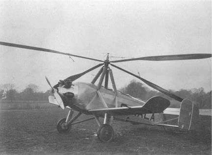
Figure 9.1 shows that de la Cierva’s early machines were basically aeroplanes having conventional aircraft controls but with a rotor added. The early rotors were hingeless and acted like gyroscopes. The problem was simply that when the conventional elevator was operated, a pitching moment was applied, but the rotor would precess this into a roll. Equally the operation of the ailerons would result in a rolling moment that would precess into a pitching motion. This was not a novel phenomenon; some World War I aircraft having rotary engines were notoriously gyroscopic and displayed precession whereby use of the elevator would cause an amount of yaw.
|
Fig. 9.1 An early de la Cierva autogyro having wings and aircraft-type control surfaces. |
De la Cierva’s free flying models were successful but they had fixed surfaces with no controls. As a result the problem was only revealed on the full-size prototypes, several of which were destroyed before flapping hinges were adopted. Blades mounted on flapping hinges cannot transfer rotor moments to the hull. With hinges fitted, the application of the conventional elevator caused the hull correctly to pitch with respect to the rotor. As was shown in Figure 4.22 this would cause the control axis to deviate from the tip path axis, resulting in an application of cyclic pitch to the rotor causing it to follow the attitude of the hull. The machine would no longer roll over when elevator controls were applied, and it would roll when the ailerons were used.
However, even if flapping hinges are fitted, this is still not enough. In translational flight, a flapping rotor will suffer from flapback due to asymmetry of lift, and will also suffer inflow and coning roll. The tip path axis will be aft of and to one side of the hub axis. The flapback is countered by propeller thrust, whereas the inflow and coning roll must be countered by steady application of opposing aileron in order to fly straight. Flapping hinges alone could not and did not control inflow and coning roll. De la Cierva soon discovered that the gyroplane is capable of very slow flight where conventional aircraft-type ailerons and elevators are ineffective. These were soon abandoned in favour of the tilting hub method of cyclic control described in section 4.15.
In a fixed pitch gyroplane application the tilting hub allows a fairly simple mechanical system. The rotor shaft is gimbal mounted and the blades have flapping hinges (and thus need dragging hinges and dragging dampers). Tilting the hub is possible because of the flapping hinges and this causes a cyclic pitch application. In stable forward flight the control axis (which is the hub axis) will be forward of the tip path axis because of flapback, and to one side because of inflow/coning roll. In other words the hub must be tilted with respect to the tip path axis.
The reader is cautioned that many of the popular explanations of blade flapping in gyroplanes are hopelessly flawed. The most common flaw is the assertion that the flapping hinges were essential to the gyroplane and by association to the helicopter. This is nonsense and the origin of it is easy to see. Many technical treatises on the gyroplane and the helicopter, for example the classic work of Gessow and Myers, analyse with respect to the control axis. To enable straight and level flight the control axis must be tilted and of course all rotors, hinged or hingeless, flap with respect to the control axis. The same erroneous account is seen in any number of general readership books. It seems that someone somewhere confused the tip path axis and the control axis and wrote an incorrect account that subsequent authors simply repeated without question.
The cyclic control requirements of the helicopter and the gyroplane are identical. As was seen in Chapter 4, the tilting hub with flapping hinges gives exactly the same cyclic control as a hingeless head with feathering hinges and a swashplate. Gyroplanes have been built with no flapping hinges and helicopters have been built with tilting hubs.
In early gyroplanes the blades were started by pulling a rope wound round a drum and brought up to speed by taxiing. Later machines drove the rotor from the engine to start it, using the ground contact to oppose torque reaction. The drive was disengaged before flight. The simple gyroplane takes off in the same way as an aircraft by accelerating along a runway, although for a much shorter distance. It can lift off as soon as the blades are turning fast enough. Using a flare, a gyroplane could lose most of its forward speed and need only a very short landing run. This allowed it to land in places from which it could not take off again. The solution was the so-called jump-take-off gyroplane. This would use the engine to drive the rotor on the ground in fine pitch until its RPM was somewhat in excess of that required for flight. By disconnecting the engine from the rotor and applying a higher pitch, the machine would jump into the
air using only stored energy in the rotor, which would suffice until forward speed had been attained.
Cierva autogyros achieved jump-start using a delta-one (see section 4.7) hinge in what was known as an autodynamic head. The inclination of the dragging hinge pin caused an interaction between the drag angle and the pitch angle. This kept the blades in low pitch as they dragged back due to engine torque. As soon as the drive was disconnected the blades would swing forwards and increase their pitch and the machine would jump into the air.
Raoul Hafner built a jump-take-off gyroplane in which the rotor head had cyclic control via a swashplate and a collective pitch control. The pilot could control the jump and also set the RRPM in flight. The machine could land vertically because the pilot could lower the collective lever to speed up the rotor during the descent and then raise it again to use the stored energy to arrest the descent just before touchdown. Hafner’s rotor head was essentially a helicopter head. Hafner went on to design the Bristol Sycamore, a practical and successful helicopter and the first British rotary wing aircraft to be given a civil Certificate of Airworthiness.
The upward inflow of the gyroplane suggests a rather different rotor design to that of the helicopter. The blade twist should be reversed compared to that of the helicopter, i. e. the root should have less pitch than the tip, although the amount of twist needed is smaller. In practice, many gyroplanes are built with no twist at all, for economy.
The rotor of the gyroplane is not supplying propulsive thrust and so the loads on the blades are reduced. Retreating blade stall is a much-reduced problem, especially if a fixed wing is provided, and as a result many early gyroplanes cruised at speeds considered high even in modern helicopters, especially those having wings.
Simple gyroplanes have two-bladed underslung teetering heads. If these have fixed pitch, the two blades can be rigidly fixed together and gimbal mounted. Cyclic pitch is applied by a single rod from the swashplate. This makes for a very light machine. However, the combination of low weight with a zero-offset rotor requires more caution on the part of the pilot, just as it does in the helicopter.
A gyroplane with a teetering head is vulnerable to a combination of low RPM and low g. Inexperienced pilots may try to dive like a fixed-wing aircraft using forward stick when they should descend by reducing power and applying aft stick. Forward cyclic will reduce RRPM. The correct recovery from low RPM/low g is a very gentle progressive application of rear cyclic. A rapid or panic application of rear cyclic at low g means that the disc tilts back without the machine following and there may be a blade strike. There have been some accidents because of this. In contrast a gyroplane with a hingeless rotor could be remarkably aerobatic.
The winged helicopter is conventional except for the addition of fixed wings (Figure 9.2). When this is done, the wing produces a proportion of the lift, and so the rotor produces less lift. However, the wing also produces drag. There will be the usual induced and profile drag as well as interference drag between the wing and the rotor.
This drag has to be balanced by thrust from the rotor. As a result the rotor tip path axis has to tilt forward further than it would without the wing. Although the vertical component of rotor lift is reduced, the horizontal component will be increased. The span of a practical wing will be less than the rotor diameter and so the wing will be less efficient than the rotor. Thus the winged helicopter is unlikely to be more efficient
|
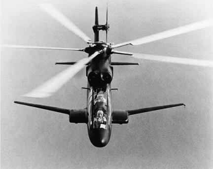
Fig. 9.2 A winged helicopter obtains some of its lift in flight from the wing. However, in the hover, the wing may cause a download. This Sikorsky S-67 prototype flew like a fighter but was not produced. |
than the pure helicopter, except at moderately high speed where the induced drag of the wing is less and the direction of the wing reaction has less rearward inclination.
The reason for fitting a wing is shown in Figure 9.3. This shows how the load factor of a rotor and a wing vary with airspeed. The wing obviously shows a square law trend with airspeed, but the rotor does not. Although the advancing blade shows this trend, the extra lift cannot be used because it would cause imbalance with the reduced lift from the retreating blade.
The simple helicopter is generally implemented as a low load factor machine because provision of a high load factor implies very poor L/D ratio in the hover. Thus if a high load factor is required in forward flight so that the helicopter can make tight banked turns, a good solution is to add a wing, as was done in the Sikorsky S-67 and the Boeing 347, neither of which entered production.
Clearly the wing will be a drawback in the hover and climb where it will cause a download. It is also a problem in autorotation where it will produce an upload. Following an engine failure at high speed, the wing will carry on lifting and it will be difficult to maintain rotor speed. A winged helicopter may also be less controllable, depending on the rotor technology. Figure 4.13 showed that a teetering head can only produce control by directing the rotor thrust so that it no longer coincides with the CM. If the thrust is reduced because the wing is providing some of the load, the control power is reduced in proportion. A hingeless rotor will suffer less from this effect because it can transfer moments to the mast.
Figure 9.4 shows the solutions Boeing tried out with the experimental 347. This was basically a CH-47 with a stretched hull, the stretch section being fitted with a wing.
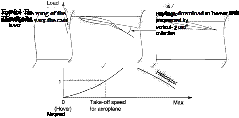 |
It was also tested with four-blade rotors. In the hover the wing could be tilted 85° to reduce download. In translational flight the goal of the wing was to offload the rotors and improve load factor. The wing had flaps that could be used to adjust camber. The outer parts of the flaps could be used differentially to act as ailerons. In Figure 9.4 it will be seen that the wing incidence was programmed from airspeed and collective pitch in such a way that the appropriate degree of rotor unloading was obtained. The flap setting was computed from the collective setting and from a g-sensor measuring acceleration normal to the cockpit floor. In a high-g manoeuvre, such as a steep turn,
increased rotor thrust would initiate the acceleration, but the g-sensor would add wing camber by lowering the flaps so that the wing lift would increase in proportion to the rotor thrust. Whilst the 347 was very manoeuvrable indeed, all of the necessary components added to the weight and complexity.
If wings are successfully to be applied to helicopters, they need to be designed in at the outset. If the wing structure can also do duty carrying fuel and/or supporting the undercarriage, the extra weight is reduced. Most helicopters have relatively poor hull shapes and finish and the hull drag is high. If an improved hull design is used, in which the usual external accessories are flush mounted, and a retracting undercarriage is employed, the drag of the hull can be reduced by an amount that makes a significant contribution to reducing the extra thrust needed by the wing.
In some machines the undercarriage retracts into sponsons outside the hull in order to avoid encroachment into the hull space. Such structures may also be used for fuel. Although not intended to be wings, it is quite common to give these an airfoil section to obtain at least some lift in return for the drag.
The compound helicopter, or gyrodyne, is one in which the rotor does not produce any forward thrust in cruise. Instead the thrust is provided by other means. Experiments were performed using turbojets, but as might be expected from momentum theory, these were a very inefficient way of producing thrust at helicopter speeds. Conventional propellers give much better results.
In gyrodynes the pitch of the thrust propeller is increased as airspeed increases so that it continues to provide forward thrust. In cruise, the cyclic control of the main rotor is used to trim the control axis so that there is sensibly no flapping and the tip path axis remains at right angles to the direction of flight. This has a number of advantages. The thrust required from the rotor is reduced as it is only carrying the weight of the machine and not overcoming drag as well. This may be reduced further by the use of stub wings. Rotor power is reduced and this reduces the weight of the transmission. However, the main advantage is aerodynamic. As the rotor remains edge-on to the airflow, there is no need to increase the blade pitch to account for inflow as speed rises. This minimizes the effect of retreating blade stall and reduces vibration, allowing a higher airspeed to be reached.
The objections to the use of a wing in an otherwise conventional helicopter mostly disappear in the compound helicopter and are replaced by advantages. The thrust to overcome the drag of the wing does not come from the rotor, but instead is supplied by the propeller. The benefit of a higher load factor is obtained along with potential for higher speed. The winged helicopter has difficulty if the engine fails at high forward speed because the wing lift prevents the rotor obtaining upflow. However, in the gyrodyne, following an engine failure at speed the propeller can be set to the windmill brake state and used to create shaft power by slowing the machine down. This power will maintain the rotor speed until the forward speed drops sufficiently to lose wing lift.
In the Fairey Gyrodyne shown in Figure 1.11 the anti-torque tail rotor is replaced by a forward-facing variable-pitch propeller mounted on a short wing at one side of the main rotor. In the hover the anti-torque propeller pulls forwards and the main rotor has to be tilted backwards using the cyclic control to prevent forward drift. The Gyrodyne captured the world speed record in 1948, but development was halted following a fatal fatigue failure having nothing to do with the compound concept.
 |
w
Fig. 9.5 With a propeller a gyrodyne can change its hover attitude using cyclic to balance prop thrust.
The Gazda Helicospeeder had a tail rotor mounted on a swivel. In the hover this would be oriented conventionally, but in forward flight the pilot could turn the tail rotor to point backwards and act as a pusher propellor. This machine still exists and has been restored by Stanley Hiller. Sikorsky also tried a similar device, which they called a Rotoprop, on a modified S-61.
In the Lockheed Cheyenne (Figure 1.12) a tail rotor and a rear-mounted pusher propeller are both provided. The tail rotor is on the end of the tail plane to clear the pusher. The propeller pitch can be controlled by a twist grip on the collective lever. In the hover the pusher propeller is typically operated in flat pitch and the tail rotor counteracts the torque as normal. However, the pusher prop can be used as a hover attitude control. Figure 9.5 shows that with prop thrust balanced by fore or aft cyclic the machine can hover nose up or nose down.
Accelerating into forward flight is not done using the propeller as it is far more effective to tilt the rotor disc as per pure helicopter practice. However, as speed builds up, the disc attitude is levelled and more power is fed to the prop. As the Cheyenne has a hingeless rotor it can provide sufficient control power even when it is off-loaded by the wing and no other controls are necessary. The Cheyenne was probably the highest performance helicopter ever built. It could do 215 knots in level flight, turn continuously at 60° bank angle, could pull 2.6 g and remain stable in negative g. The fact that the Cheyenne didn’t enter production again had nothing to do with the compound concept.
In the Piasecki Pathfinder the rear prop is mounted in a ring duct equipped with deflectable vanes to provide anti-torque thrust for hovering. Whilst adequate for civil operations it is unlikely that such an arrangement would meet military crosswind hover requirements. The Pathfinder’s ring duct also has adjustable horizontal vanes. In cruise these can be trimmed so that the hull is absolutely level for minimum drag even if the CM is not aligned with the rotor shaft. The rotor is then providing axial thrust only and so alternating loads on the mast are minimized.
The compound helicopter offers a tangible way of improving the performance of the helicopter, particularly in the area of forward speed. Compound helicopters have not yet reached the market, but this is not because of any fundamental performance problem. If there is a rotary wing technology deserving to be revisited with modern materials
and control systems then this is it. A tail-mounted pusher propeller for forward flight would be naturally complemented by a NOTAR system for hovering, leading to a very clean external appearance with low drag.
A convertiplane changes its operating principle according to the flight regime, most obviously between hover and cruise. The Fairey Rotodyne (Figure 1.11) is a conver – tiplane. This machine has two turboprop engines that in addition to driving variable pitch propellers can also produce significant amounts of compressed air. In the hover the compressed air is fed along the rotor blades and fuel is burned at the tips to drive the rotor. There is no torque reaction and yaw control is obtained using differential propeller pitch.
The tip jet drive is inefficient, but is only used for take-off and landing. Once forward speed has been obtained, the rotor drive is switched off and the rotor is tilted back so the machine becomes a gyroplane. The rotor is partially unloaded by the wing. Landing is achieved by reigniting the tip jets and reverting to helicopter mode, although landing on a runway in gyroplane mode is also possible.
The winged McDonnell XV-1 has a single piston engine driving either a propeller or an air compressor. In order to hover the compressor output is fed along the blades to tip jets as in the Rotodyne. No yaw control could be obtained with a single prop, and instead a pair of small fixed pitch tail rotors is installed, powered by small reversible hydraulic motors. The XV-1 can then take off as a helicopter. In forward flight the engine power can be diverted to the prop so that the machine becomes a compound gyroplane.
The XV-1 has a substantial wing area and full conventional aircraft controls and in cruise these will become functional. The fore-and-aft cyclic control is then automatically adjusted to control rotor speed. This is reduced to 50% of the hover RPM, so that the wing is carrying about 80% of the machine weight. Thus the XV-1 can fly as a helicopter, a gyroplane or an airplane.
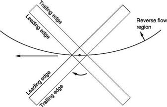
Following the progression of unloading the rotor in forward flight, the next step in the view of some designers is to dispense with the rotor altogether. There have been numerous proposals. A two-blade rotor is stopped transversely in flight to become a wing, a four-blade rotor becomes an X-wing, a rotor folds and retracts into the hull. All of these proposals suffer from the same practical difficulty – as the rotor slows down it loses the centrifugal stiffening effect. As has been seen earlier in this book, as a rotor slows down it ceases to be gyroscopic and the phase lag starts to reduce from 90°. This causes a control problem. A more serious difficulty shown in Figure 9.6 is that at some stage a near-stationary rotor blade will have significant sweep forward and this is an unstable condition. In conventional wings and blades flutter is avoided by bringing the mass centroid towards the leading edge. However, at low rotor speed the reverse flow region would envelop the retreating blade such that leading and trailing edges interchange so this technique cannot be used. The blade and hub would need to be immensely rigid in torsion and bending to survive the loads. As a result no practical machine has emerged and it is unlikely that one will.
The only in-flight rotor-folding technique that appears viable is to tilt the rotor backwards and to feather the blades. As the rotor slows down it will cone up 90° and ultimately stop with the blades trailing in the slipstream. However, if the rotor is going to be tilted, why not use it as a propeller?
|
Fig. 9.6 The flaw in stopped rotor proposals. As rotor speed falls, the reverse flow region becomes enormous and leading and trailing edges interchange. |
Tip jet convertiplanes are interesting and educational, but are unacceptably noisy as production items. More significantly, developments in fixed-wing STOL technology have delivered simpler solutions in many applications. Stopping the rotor in flight is simply too difficult. Consequently most of the recent progress made in convertiplanes has been in machines that tilt the rotors in some way to become propellers creating forward thrust. This is an elegant approach because there are no redundant propellers in the hover and no redundant rotors in cruise.
A prop rotor or tilt rotor machine can take off like a helicopter, but by turning the rotors about a horizontal axis forward flight will be achieved. When the rotor axes are horizontal there will be no rotor lift at all and the wing must produce 100% of the lift. In this mode the tilt rotor is an aeroplane with large propellers. Compared to a helicopter, drag is reduced considerably and the top speed and range are significantly improved. The load factor also becomes that of an airplane and so the tilt rotor should be highly manoeuvrable.
A rotor that provides enough hover thrust will be somewhat overspecified in forward flight and will be inefficient because it will work at a low L/D ratio with a high profile drag penalty. The solution currently adopted is to make the cruise more efficient by reducing the rotor size. This increases the disc loading in hover, and drives up the downwash velocity and the power required, but this power is not used for very long. It may be an advantage to use different RPM in the hover and in forward flight. With the rotor always in axial flow, the alternating forces experienced by the helicopter blade do not exist and the rotor does not need to be detuned against vibration. It is thus quite easy to change the rotor RPM for cruise.
The ideal would be a variable diameter rotor and although the forces involved are considerable this is not considered insoluble. With high disc loading and a wing, the tilt rotor is not expected to have good autorotation performance and it would appear inadvisable to rely on a single engine.
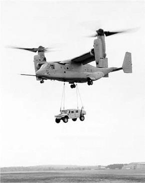
The Bell-Boeing Osprey (Figure 9.7) tilt rotor is a true helicopter in the hover. It has contra-rotating rotors that have cyclic and collective pitch. There are two engines, one in each wing tip nacelle. The entire engine and transmission tilts with the rotor. To give protection against engine failure the two rotors are connected by a cross shaft so that
|
Fig. 9.7 The Bell-Boeing Osprey tilt rotor is a true side-by-side helicopter in the hover. |
either engine can drive both rotors. In the wing centre section the cross shaft drives accessories.
In the hover, the pitch axis is controlled with fore-and-aft cyclic applied equally to both rotors. Yaw is controlled by applying fore-and-aft cyclic in opposite directions. The roll control requires differential collective pitch. In addition to the cyclic and collective controls, the pilot has a control that can alter the angle of the two engine nacelles. These are synchronized so they will always have the same angle. From the hover, thrust is increased and the nacelles are brought down. Initially the download on the tail plane will cause the nose to rise, but as speed builds up and the dynamic pressure on the wing and tail increases, the machine becomes an aeroplane and responds to its control surfaces. The cyclic control of the rotor pitch is unnecessary in forward flight.
The wing forms an obstruction in the hover and in the Osprey the leading and trailing edges will both fold to present the least area to the downwash. As the angle of relative airflow seen by the wing changes, first the leading edge and then the trailing edge will fold back to the forward flight position. A disadvantage of the tilt rotor is that in the hover the lift is applied at the wing tips and the wing is highly stressed.
One of the enabling technologies that turned a research tool into the Osprey is an extremely complex electronic control system that recognizes the flight conditions and automatically directs the pilot’s control movements to swashplates or control surfaces or both as necessary. This could probably not have been implemented mechanically. The extensive use of composites has led to an airframe light enough to allow a useful payload.
An alternative to the tilt rotor is the tilt wing in which the wing and rotors form a single assembly that tilts. As the wing chord is vertical in the hover the obstruction of the downwash will be reduced. In this attitude the wing forms a deep beam and will naturally be very stiff. The wing needs no folding flap mechanism and therefore will be less expensive. It may be possible to use the wing ailerons as a yaw control in the hover, leading to an approach in which the rotors have no cyclic control at all, but become variable pitch propellers. Hover roll control is then by differential collective, but control of the pitch axis in the hover requires an additional rotor at the tail which is only powered for the hover. The requirement for a horizontal tail rotor somewhat offsets the saving in complexity due to eliminating the use of cyclic pitch on the main rotors.
Whilst such an approach may be suitable for a civil machine, it is unlikely that the more stringent requirements of the military could be met, specifically the hover performance in a wind where the vertical wing is a drawback. The tilt wing also requires more caution in the transition from aircraft to helicopter mode where the prop rotor thrust and wing angle have to be carefully adjusted as a function of the airspeed.
Multi-rotor helicopters have advantages in some niches of the market, but are significantly less common than the conventional type partly because of the added complexity and partly because additional skills are needed to develop them. It is often the case that one individual has perceived a particular advantage of a configuration and perfected it for a particular niche. That niche having been filled, no other manufacturer then seeks to compete. As a result each type of machine will be associated with a particular manufacturer. Thus the tandem is associated with Vertol/Boeing, the coaxial with Kamov and the synchropter with Kaman.
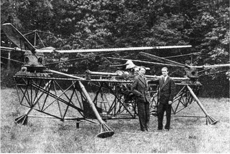
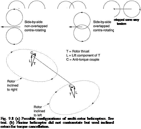
Figure 9.8(a) shows that there are a number of possibilities with two rotors. The rotors may or may not overlap, and they may be placed in tandem or transversely to the direction of flight. If they do not overlap, the rotors may turn in the same direction or may contra-rotate. If the rotors turn the same way, they must be inclined away from the vertical to counteract torque as shown in Figure 9.8(b). Nicolas Florine successfully flew a machine of this kind in Belgium in 1933 as Figure 9.9 shows. In those days helicopter dynamics were poorly understood and Florine chose same-way rotation because the gyroscopic stability of the rotors would not cancel. Florine used hingeless rotors and the same-way rotation would also have minimized the stress on the hull. Test flights proved Florine right as in its day it was probably the most stable helicopter in existence. The Cierva Air Horse shown in Figure 9.10 had three rotors which all turned the same way. Torque cancellation was obtained using the Florine principle.
The side-by-side arrangement of contra-rotating rotors has some advantages in forward flight because it improves the aspect ratio of the ‘disc’ and reduces the induced power needed. Heinrich Focke’s Fw 61 was a machine of this type and was probably the first helicopter in the world to progress from the flying test bed into a truly flyable machine. This machine achieved a degree of notoriety in 1938 when it was extensively demonstrated as a Nazi success symbol flown by Hanna Reitsch. This should not
 |
(b)
detract from Focke’s technical achievement. The Fw-61 used the hull of a Focke-Wulf fixed-wing plane, with a forward-mounted radial engine carrying a small airscrew for cooling. Behind the engine was a gearbox that routed power out to each rotor along slim drive shafts.
Focke’s next machine was the Fa 223 which first flew in 1940 and reached production in 1942. By this time Focke had left Focke-Wulf and formed a company with Gerd Achgelis, hence the designation Fa. This was a large side-by-side machine powered by a centrally mounted 1000 hp radial engine. With 12 metre diameter rotors it had a payload of 2000 kg, meaning that it could almost have lifted its Sikorsky contemporary. The Fa 223 reached 7500 metres, flew at 200 kph and was a great technical success, although few orders were fulfilled because of bombing raids on the factories. After the
|
Fig. 9.9 The Florine helicopter flew very well but development was hampered by lack of funding |
|
Fig. 9.10 The Cierva Air Horse had three rotors turning the same way using the Florine principle for torque cancellation. (AugustaWestland) |
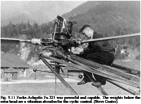 |
war the Fa 223 became the first helicopter to fly the English channel when the RAF recovered a captured machine (Figure 9.11).
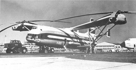
The largest helicopter in the world was also a side-by-side. The Mil V-12 (Figure 9.12) used the drive trains and rotors of the Mil 6, itself a huge machine, with the rotation of one system reversed. Side-by-side helicopters have the disadvantage that the pylon structure needed to carry the rotors invariably causes drag. Considerable masses are cantilevered at the end of these pylons and it is also difficult to obtain enough structural rigidity.
The coaxial helicopter configuration was frequently seen in the experimental period as the contra-rotation offered torque cancellation. However, the coaxial machine also has some idiosyncrasies in autorotation and once the single rotor machine was perfected the coaxial was simply too complicated except for special applications. For use on naval vessels, where hangar space is limited, the absence of the tail rotor allows a more compact hull for a given load capacity. The Kamov machines demonstrate that amply. The coaxial configuration has also been used with success on unmanned helicopters.
Provided that the two rotors are not too far apart, the coaxial rotor system in the hover behaves very much like a single rotor with the same total solidity. This is not true if the vertical separation is significant, because if the wake of the upper rotor has started to contract the lower rotor will encounter increased inflow velocity and will
|
Fig. 9.12 Mil V-12 was the biggest helicopter ever built but did not enter production. |
|
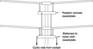
Fig. 9.13 Control system of coaxial helicopter is inevitable complicated, needing two swashplates. Collective controls usually run inside the mast. |
thus need more power. However, this power loss may be cancelled by the fact that the lower rotor recovers the swirl energy of the upper rotor.
The coaxial helicopter needs two swashplates as can be seen in Figure 9.13. The first connects the stationary cyclic controls to the lower rotor, and the second allows the cyclic control to pass from the lower rotor to the upper rotor. The cyclic control thus tilts both rotors in the same sense. The collective control will apply the same pitch change to both rotors. Yaw control is commonly obtained by differentially changing the collective pitch. This requires rotating mixers to add the cyclic inputs from the swashplates to the collective inputs that generally pass up the centre of the mast. The resulting mechanism is incredibly complicated as a study of a Kamov rotor head will show.
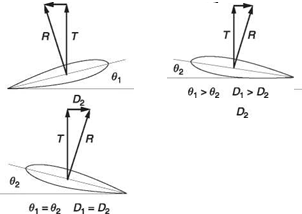 |
Fig. 9.14 In powered flight, with equal pitch on both rotors there is no net torque. Increasing the pitch of the upper rotor causes its blade reaction to rotate back whilst that of the other rotor rotates forward and a yaw results.
Figure 9.14 shows how the yaw control works. The machine is in a power-on condition so the blade reactions will be tilted back with respect to the shaft axis. The vector sum of these two reactions is vertical so there is no net torque and no yaw effect. Figure 9.14 shows that increasing the pitch of the upper blade will increase the thrust and tilt it back against the direction of rotation. At the same time the pitch of the lower blade is reduced. This will reduce the thrust and tilt it forwards, with the direction of rotation. The vector sum will now be non-vertical so that there is a net torque turning the hull the same way as the rotor whose pitch has been reduced.
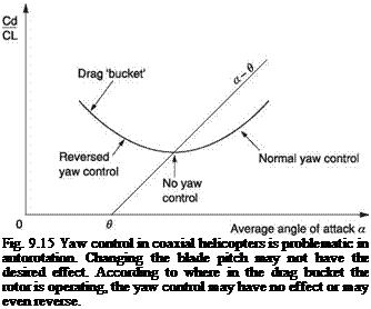
In autorotation, the yaw control of a coaxial machine using differential collective is problematic as it may have no effect, or a reverse effect. This was initially not appreciated, and caused some hair-raising moments. Figure 3.14 introduced the autorotation diagram and Figure 9.15 shows an autorotation diagram appropriate for coaxial helicopters. Here the horizontal axis is the average angle of attack of the two rotors. In autorotation, the blade pitch will be chosen for the best rotor L/D at the bottom of the drag bucket. In most helicopters, the lower collective stop is set at the intersection of the a-в line and the drag bucket. However, when differential collective is used for yaw, the pitch of one of the rotors can be even less and so operation can be to the left of the intersection. The problem is that when operating at L/Dmax., an increase in pitch or a decrease in pitch will have the same effect: the rotor experiences more drag and slows down. At some collective settings there is no yaw control at all. To make matters worse, helicopter designers often select blade sections having a relatively flat bottomed drag bucket. If the collective stop is slightly lower than the setting for L/Dmax., increasing the pitch will reduce drag and reducing pitch will increase it. As a result the yaw control reverses.
To overcome the problem, coaxial helicopters need a significant amount of vertical tail area to give yaw stability in autorotation. The fins are often slatted to prevent stalling at high angles of attack. In some machines a mechanism is fitted so that the action of the pedals is automatically reversed when the collective is fully lowered.
An alternative yaw control mechanism for coaxial helicopters was seen on the Gyrodyne helicopter. This consisted of drag brakes in the blade tips that could be
 |
extended in one or other rotor. This approach has the advantage that there is no reversal in autorotation.
Another suggestion for yaw control is the use of a friction brake between one or other of the rotor shafts and the hull. A moment’s thought will reveal that with a conventional transmission this would not work. If the coaxial helicopter simply has two shafts driven in opposite directions at the same speed by the same input shaft, applying a brake to one of these has no yaw effect at all, but simply slows down both rotors. In order to use brakes, the two rotors have to be driven with a differential gearbox that allows one rotor to speed up as the other slows down. Subject to this complexity, the friction brake system has the advantage of significant reduction of rotating linkage as there is then no need for differential collective or tip drag brakes. There is also no control reversal.
In forward flight the coaxial helicopter has the advantage that the retreating blade of one rotor is on the opposite side to the retreating blade of the other rotor. This means that if a suitably rigid rotor head assembly can be built, the lift trough due to a retreating blade can be overcome by the lift from the advancing blade of the other rotor and higher forward speed becomes possible.
The synchropter is a helicopter having two contra-rotating synchronized rotors mounted side by side that are deeply meshed. Figure 1.17 showed that the rotor shafts are set on pylons and are tilted outwards so that the blades of one rotor can pass over the head of the other. In machines having two-bladed rotors the blades are phased 90° apart so that one blade is safely oriented fore and aft when the other passes overhead. The synchropter principle was invented by Anton Flettner and used on his successful Kolibri (hummingbird) helicopter.
Although there is no tail rotor, there is no consequent safety advantage. The outward tilt causes the rotors to pass close to the ground at the sides. Synchropters are usually placarded with warnings to ground personnel to approach from the front. Aerodynamically the synchropter is similar to the coaxial helicopter in that the efficiency loss of
a lower blade working in the downwash of an upper blade is offset by swirl recovery. The lateral separation of the rotors means that the disc area is greater than the area of a single rotor and this reduces the disc loading and the induced power needed, although some of the advantage is lost because the rotor thrusts do not align. The horizontal components of the rotor thrusts are in opposition and some power is wasted. In forward flight the rotor separation gives a better disc aspect ratio.
From a performance standpoint, the twin rotor heads cause a drag penalty and the synchropter is not appropriate for high speed. However, as the synchropter is practically limited to two-blade rotors, it naturally suggests low solidity and disc loading which is the ideal for low speed, high altitude work or heavy lifting.
The synchropter is controlled in a similar way to the coaxial helicopter in that differential collective pitch is used as a yaw control. This will be subject to reversal in autorotation as for the coaxial helicopter. Some yaw control is also possible by the use of differential fore-and-aft cyclic, although the short distance between the rotor heads makes this ineffective. The usual fore-and-aft cyclic control affects both rotors equally, but the lateral cyclic may be adapted so that the discs tilt outwards more than they tilt inwards in order to preserve clearance between the heads and the blades. Generally synchropters have poor yaw control and require a large amount of fin area.
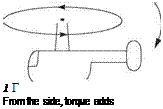
The outward tilt of the rotors means that the torque cancellation is not perfect. It can be seen from Figure 9.16 that although the torque cancels in the vertical axis, there is a component of rotor torque in the horizontal axis which is the same for both rotors and therefore adds. If the synchropter is arranged to have the advancing blades on the inside, the torque reaction will tend to pitch the hull nose up until the CM is far enough ahead of the masts to counter the torque. In the hover this will require the application of forward cyclic so that the rotor thrust remains vertical. In forward flight the forward CM is a useful stability aid. As forward speed builds up, the drag on the hull will act below the rotor heads and produce a couple tending to tilt the hull nose down. The rotor torque will counter this. Consequently there is a correct way for synchropter rotors to turn, i. e. with the advancing blades on the inside.
 |
 |
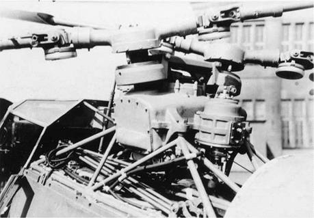
The Flettner 282 Kolibri (Figure 1.4) was not only the world’s first synchropter, it was also the world’s first production helicopter, beating Sikorsky’s R-4 by several months as well as being technically superior. The Kolibri had very closely meshed two-bladed rotors. Figure 9.17 shows that these were fully articulated with friction disc dragging dampers. There was substantial flapping hinge offset so that the rotor blades would not flap into contact with the opposite head. This allowed space for the feathering hinge to be mounted inboard. The swashplates and pitch links were a compact and elegant arrangement. A 160 hp BMW radial aircraft engine mounted in the conventional aircraft attitude drove the transmission through an inclined shaft. The foot pedals
Fig. 9.16 In the synchropter there is a component of torque along a horizontal axis.
|
Fig. 9.17 The transmission and rotor heads of the Flettner Kolibri. (Steve Coates) |
operated the rudder as well as the rotor yaw mechanism. The pilot could also change the angle of incidence of the tail plane.
The Kolibri was an advanced machine; it had adequate power and was highly manoeuvrable. In a mock dogfight with a Focke-Wulf 190 the fighter was unable to get the Kolibri in it sights. Following the end of the war, a significant amount of advanced German technology found its way to various allied countries. In the USA, Charles Kaman recognized the potential of the synchropter principle and combined it with the servo-tab control system to produce a highly successful series of machines. The Kellet Co. made some synchropters with three-bladed rotors but these had blade contact problems and did not reach production.
Kaman’s early synchropters were piston engine powered, culminating in the HOK-1 into which was shoehorned a 600 hp radial aircraft engine, which still wasn’t powerful enough for some purposes. The piston engine simply isn’t suitable for helicopters above a certain size. The world’s first turbine engine helicopter was a Kaman synchropter, as was the world’s first twin turbine helicopter. Kaman’s most well-known synchropter is the H-43B, aka Husky. It was also known as the Pedro, after a call sign originally used at a Texas air base. The Husky was basically a redesign of the piston engined H-43A using a turbine and it became a classic piece of industrial design. The compact turbine engine was placed on the roof behind the transmission, resulting in a large, open cabin accessed by rear clamshell doors as well as sliding doors at the side. The servo-tab control system meant that the forces needed from the pilot were quite low even though there was no power assistance.
The yaw control was aided by relatively wide rotor head spacing and an automatic yaw reverser to make the pedals work in the correct sense in autorotation. The Husky also had an impressive array of vertical fin area to maintain directional stability when
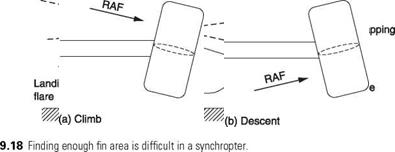
the yaw control was fragile. The provision of a large fin area is a problem in coaxial helicopters and synchropters as Figure 9.18 shows. There is a wedge of space in which the fins can exist. The top of the wedge is defined by the rearmost flapping of the rotors and the bottom of the wedge is defined by where the ground will be in a flared landing.
The difficulty is that the further back the fin area is, the more effective it is. However, the further back the fin, the smaller it has to be. The only solution is to use a number of parallel fins. The early Huskys had a habit of knocking the tops off their fins. This was solved with a redesign, although expedience dictated making the top and bottom ends of the fins from glass fibre that would disintegrate in any extreme manoeuvre without causing any further damage.
Another difficulty with fins in helicopters is the wide range of directions the airflow can come from. This makes it hard to maintain the optimum aspect ratio of the fin. The Kaman Husky solved this problem very nicely by mounting the fins on a floating elevator that would align itself with the airflow. Figure 9.19 shows that the fins were then always correctly oriented.
The Husky had very low disc loading giving it excellent lifting ability and high altitude performance. In 1961 a Husky reached almost 33 000 feet! The torque cancelling of the synchropter meant that pilot workload was quite moderate and the lack of a tail rotor meant it could land in difficult terrain. The Husky distinguished itself as a rescue helicopter, particularly where crashed aircraft had caught fire. The Husky would hover overhead, using the downwash to blow flames clear of the fire fighters and victims.
 |
The Husky was superseded by conventional turbine helicopters that were faster, but a number of surplus machines found their way into logging and aerial work where speed was not of the essence. Their success in this niche led Kaman to produce the
Fig. 9.19 The fins of the Husky are mounted on a floating tail plane so that they always align with airflow to offer their best aspect ratio.
K-Max: basically the mechanics of a Husky with a minimalist single-seat hull optimized for underslung load working. The K-Max is the only synchropter currently in production. As the K-Max is a single-seater, a number of Huskys have been refurbished to act as trainers.
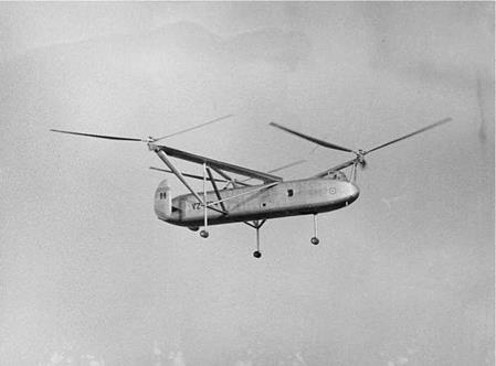
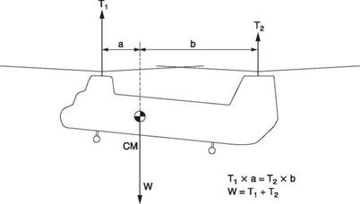
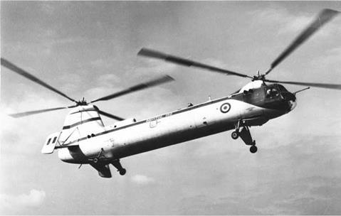
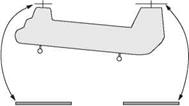
Once the stress-reducing benefits of blade articulation became known, contra-rotation could be adopted in the tandem. This largely cancels torque reaction. Claims will often be seen that because there is no tail rotor to waste power, the tandem must be more efficient than the conventional helicopter. This is not necessarily true because the two rotor discs may overlap reducing the total disc area. In fact the real advantages of the tandem are that the position of the centre of mass is much less critical than in single rotor machines and that hovering is much less sensitive to wind direction. In military operations the ability to hover on any heading, load in a hurry and simply fly off saves valuable time. Later Chinooks have three load hooks in line beneath the hull so that supplies can be taken to three locations in one flight. This would be impossible with a single rotor machine because it could not handle the CM travel as the loads were dropped off one by one. Figure 9.20 shows that if the CM position is not in the centre the trim will be operated so that the rotor at the ‘heavy’ end produces more thrust and the other rotor produces less. A secondary effect of this condition will be that there is not a perfect torque balance and some yaw control will be required.
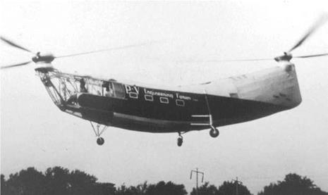
It is quite possible to construct a tandem rotor machine in which the two rotor discs are separated. The Florine machines and the Piasecki ‘Dogship’ (Figure 9.21) had this configuration. This approach results in a long and possibly heavy hull and a physically large machine requiring a lot of hangar space: a drawback in naval operations. As a result in modern tandems the two discs will be significantly overlapped such that the distance between the rotor heads is less than the rotor diameter. The rotors must be synchronized by a shaft joining the front and rear gearboxes so that, like the synchropter, the two rotors can share the same airspace without clashing.
|
Fig. 9.20 The tandem configuration can deal with longitudinal CM offsets using a different amount of thrust on each rotor. |
|
Fig. 9.21 The Dogship was Piasecki’s first tandem rotor helicopter and was widely demonstrated to attract interest in the principle. Itwas the forerunner of the ‘flying bananas’ and the Chinook. (Boeing) |
|
Starboard engine
Port engine Fig. 9.22 The transmission system of the Chinook showing the synchronizing shaft between the rotors and the twin engines. |
Chapter 5 described the interaction between the main and tail rotor of a conventional helicopter. In the hover it was seen to be highly variable with wind direction, whereas in translational flight there was a beneficial weathercocking effect. In the tandem the interference between the two rotors in the hover is beneficially almost independent of wind direction, whereas in forward flight it is detrimental to stability. Consequently it is simplistic to claim that one configuration is better than another. In some areas the conventional approach is superior, but in other areas the tandem wins.
Figure 9.22 shows the transmission arrangement of the CH-47 (Chinook) in which the two engines drive the synchronizing shaft via one-way clutches so that either engine can drive both rotors. It is interesting to note that except for the use of piston engines, the Florine III of 1935 had the same transmission layout. As the dominant masses and the rotor forces are both concentrated at the ends of the hull, the structure needs to be stiff against bending and torsion. The loss of disc area due to the overlap of the two
discs causes some loss of aerodynamic efficiency, generally of the same order as the loss due to driving the tail rotor in a conventional machine. However, the shorter hull will be lighter and have less area exposed to downwash so the overall lifting capacity remains about the same.
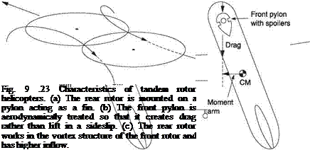 |
In forward flight the tip path axes must be tilted forward just as in a single rotor machine to obtain a forward component of thrust. Figure 9.23(a) shows that in practice
the rotors are mounted so that they remain substantially in the same plane in translation. This allows the rear rotor to operate in relatively clean air. In order to keep the cabin level and to provide blade clearance, the rear rotor is mounted on a pylon. It is a characteristic of this approach that ground clearance of the front rotor disc is relatively small. However, the poor clearance exists directly in the pilot’s field of view. With no tail rotor to weathercock and a short moment arm, a large amount of fin area is usually needed and even then tandem rotor machines are aerodynamically marginal in yaw.
This is not all bad because many operations require the machine to hover at an arbitrary orientation to the prevailing wind and the tandem does that very well. The rear pylon is always shaped to act as a substantial fin and the front pylon may have aerodynamic treatment to stop it acting as a fin. This may consist of irregularities designed to cause early flow separation when the relative airflow is off the fore-and-aft axis. Figure 9.23(b) shows that the resulting drag causes a smaller yaw component than if the pylon caused lift.
Figure 9.23(c) shows that the rear rotor is affected by the front rotor vortices in translational flight. Effectively the rear rotor is operating with a greater inflow velocity than the front rotor. In a machine with a central CM, both rotors will need to produce the same amount of lift. To develop the same thrust the rear rotor will need to use a higher blade pitch and will absorb more torque because of the higher inflow. The swirl of the forward rotor also acts asymmetrically on the hull. For these reasons the torque is not precisely balanced in translation. One prototype tandem helicopter could not initially fly in a straight line in translational flight because these effects were more powerful than the yaw control. Once the nature of the problem was understood a solution was not far behind.
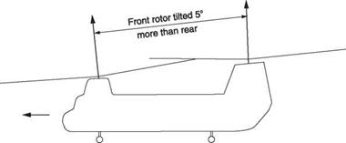
There are ways to mitigate the problem. An obvious suggestion would be to move the CM forward. Whilst this would work, it somewhat negates the advantage of CM position freedom. In practice, the two rotors can be set at a different angle. Figure 9.24 shows that the front rotor shaft may be inclined forward with respect to the rear. This is done on the CH-47 in which there is a 5° difference between the angles of the shafts. This increases the inflow seen by the front rotor and decreases the lift component of its thrust, whereas the inflow of the rear rotor is reduced and the lift component of its thrust is greater. Another possibility is that the fin can be built with an integral camber so that in translational flight it produces a side thrust. The cambered fin of the CH-46 is obvious in a rear view.
The interference between the rotors can be minimized by flying the machine sideways as this increases the diameter of the stream tube and improves the aspect ratio,
|
Fig. 9.24 The front and rear rotor shafts may be inclined at different angles. |
giving greater translational lift. This technique works well in a steep climb. The drag of the broadside hull will be a problem as speed builds up. However, some advantage can still be gained by flying with sideslip; 15° is a typical figure. Some piston-engine tandems used as plane guards during carrier operations were operated in this way as standard procedure. In a twin-engine machine, sideslip operation may be used to handle one-engine-inoperative conditions. The direction of sideslip is important as the downwash from the front rotor is not symmetrical.
The tandem rotor market is one many manufacturers have stayed away from. In the UK, the most successful tandem was the Bristol Belvedere (Figure 9.25) designed by Raoul Hafner which started life mechanically as a pair of Sycamore mechanics with a synchronizing shaft and which subsequently evolved into a capable twin turbine. Yakovlev built a large tandem machine in the USSR but this was not successful. In the USA Bell built the HSL but it did not enter production. The name most closely associated with the tandem is that of Frank Piasecki whose early fragile canvas covered creations, dubbed ‘flying bananas’ from the bent hull needed for rotor clearance, matured into the enduring CH-46 and CH-47.
The CH-46 is about as attractive as a tandem can get and when it was first built its good lifting capacity and amphibious capability made it a favourite with the US Navy who use it for vertical replenishment (VERTREP) which is military-speak for moving material from one ship to another suspended below a helicopter. The army liked the concept but wanted something with a bigger cabin and the CH-47 was born.
The CH-47 Chinook is a superb piece of industrial design by any reference. The basic design dates from 1961 and because it is fundamentally well founded it is simply upgraded from time to time. It is amazingly versatile and genuinely amphibious. In other words it can operate normally from water rather than just floating in an emergency. The absence of a tail rotor means that it can land in scrub.
|
Fig. 9.25 The Bristol Belvedere was a twin turbine military machine that was successful in service despite frequent fires caused by its absurd engine starting system. (AugustaWestland) |
For easy loading, the Chinook is designed around a constant cross-section cabin with a rear ramp. The fuel and undercarriage are housed in two long side sponsons that provide stability on water and cause no intrusion into the load space. For similar reasons the engines are placed above the cabin, and the synchronizing shaft and control pushrods run in a hump or spine above the cabin. The immense rear pylon/fin is used to house the engine combining transmission, the oil cooler, the rear gearbox and swashplate actuators, the APU and almost anything else that needs a home with the result that the hull is kept free for payload.
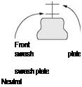
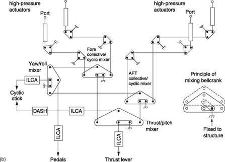
The control system of the tandem rotor helicopter is more complex than in a tail rotor-type machine. The rotor heads need to be articulated for reasons that will be seen. Figure 9.26(a) shows that the swashplates tilt simultaneously for roll control and tilt differentially for yaw control and to oppose any residual torque imbalance. They move up and down together for thrust control and differentially for fore-and-aft (pitch) control and to handle CM shifts. All of this is achieved in a Chinook in a diabolical mechanical mixer located in the control closet behind the port pilot’s seat which takes the inputs from the pedals, cyclic stick and thrust lever (tandemspeak for collective) in the cockpit floor and adds and subtracts in various ways to obtain four pushrod outputs which go into the roof, one to control each side of each swashplate. The conceptual mechanism is shown in Figure 9.26(b). The autopilot is incorporated in an unusual fashion. Electrical autopilot signals and mechanical pilot inputs are supplied to small duplicated hydraulic actuators in the control closet located before the control mixer. These are called integrated lower control actuators (ILCA) and they operate the control mixer. The mixer pushrod outputs are then led to duplicated high pressure hydraulic actuators at the swashplates. These actuators have mechanical inputs. This approach allows a conventional autopilot to output yaw, pitch, roll and thrust commands to the airframe. If the autopilot had to control the swashplate actuators directly, an autopilot mixer would have been needed.
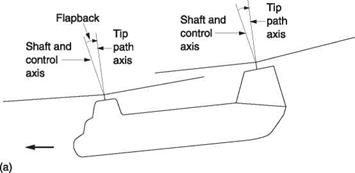
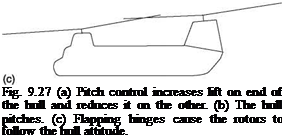
When the cyclic stick is pushed forward, differential collective pitch increases the thrust of the rear rotor relative to the front rotor (Figure 9.27(a)). The hull is tilted forward about the pitch axis (b) and this makes both rotor shafts tilt relative to the tip path axes. This hub tilt causes a cyclic feathering effect such that both rotors pitch forward to follow the hull (c). This is the control mechanism used in hovering.
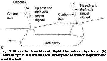
In order to move into forward flight, forward differential collective is maintained so the machine gathers speed. The lift asymmetry due to translational flight in both rotors will cause the tip path axes to flap back with respect to the two control axes as shown in Figure 9.28(a). At a given airspeed, this results in a larger change in cabin floor angle, reduced blade clearance at the rear of the front rotor, more hull parasite drag and a large amplitude of flapping and dragging at the rotor heads because of the large differences between the tip path and shaft axes.
Thus in practice a tandem helicopter requires means to apply forward cyclic control to both swashplates in translational flight as a function of airspeed. Figure 9.28(b) shows that this results in closer alignment between the tip path and shaft axes, reducing the amount of flapping and dragging and improving the clearance of the front rotor. In the Chinook the fore-and-aft cyclic controls are not connected to the cyclic stick. Instead they are driven by an automatic system which is airspeed sensitive and starts to apply forward cyclic at speeds above about 70 knots. The application of forward cyclic to reduce flapping will also tend to increase the airspeed. To compensate for this, a series actuator, known as the DASH actuator, in the fore-and-aft cyclic pushrod is also operated by the automatic system in such a way that the pilot sees a fairly constant positive gradient between cyclic stick position and airspeed which is not impaired by the automatic forward cyclic control of the swashplates. The DASH actuator can be seen in Figure 9.26(b).
![]()
 |
|||||
|
|||||
|
|||||
|
|||||
|
|||||
|
|||||
|
|
|||||
|
|
||||
|
|||||
|
|
|
|||
|
![]()

![]()

![]()
|
|
|
|
|
|
The yaw control is by differential tilt of the rotor thrust and clearly if there is no rotor thrust there will be no yaw couple. If rotor thrust reverses the yaw control will reverse. Whilst this is not a problem in most flight conditions, a zero-g pushover could result in loss of yaw control. A crop-dusting turn or return-to-target manoeuvre is also difficult for a tandem because when the hull is pointing straight up after the first quarter loop the rotors need to be set to flat pitch and this removes the yaw authority. Consequently the tandem will perform a variation on the manoeuvre in which the yaw is commenced during the quarter loop. Momentum carries the yaw on during the flat pitch phase.
The tandem is generally designed to have a level cabin in translational flight and when at rest on the ground. This means that in the hover the cabin will slope down to the rear and the machine must touch down with the rear wheels first. This allows an interesting taxi mode where the rear wheels are carrying a significant weight but the front wheels are clear of the ground. Forward speed can be controlled by rear wheel brake and steering is possible by applying the brakes differentially.
The waterborne characteristics of a tandem are worth a few comments. The contrarotation means that the rotors can be started and stopped whilst afloat without the machine rotating as a single main rotor machine would. The built-in tip path plane tilt causes a tendency to forward motion when the hull is floating level. When afloat the acrylic cockpit chin windows are partially submerged, and whilst this is not a problem whilst stationary, water taxiing at speed will put them under tremendous stress. To avoid this, pilots will lift the nose in a water taxi. The floor of the cabin is sealed to act as a raft for use on water and the ramp can be lowered whilst afloat to deploy or recover small boats or swimmers.
In the tandem rotor helicopter the rotor heads are designed to meet different requirements. The yaw control is obtained by tilting the two rotor discs laterally in opposite directions. Effective yaw requires that the tip path axes actually make a significant tilt and the flapping hinges are needed to allow this to happen. If conventional heads with significant flapping hinge offset are used, the result of an application of the yaw control is a serious twisting couple applied to the fuselage. Thus for a tandem rotor helicopter, the flapping hinge offset needs to be significantly reduced. This need not reduce the roll response, because a roll is obtained by applying lateral cyclic to both rotors in the same sense. As there are two rotors, each rotor only needs to apply half the roll moment. In order to prevent heavy underslung loads reducing the lateral cyclic authority the main load hook is on rollers and can traverse a curved lateral beam whose centre of curvature is near a line joining the rotorheads.
In the Chinook, the flapping hinges are provided with a relatively small offset for the above reasons. If the dragging hinges were coincident with the flapping hinges there would be a large drag angle change between the power-on and autorotation states and there would be little space for drag dampers. Instead the dragging hinges are placed outboard of the feathering hinges. This arrangement worksvery well and the only drawback is that when the blades are stationary gravity causes them to swing about the dragging bearing. These are not necessarily vertical, being outboard of the feathering bearings.
 |
In some cases putting a pilot in a helicopter is not the right thing to do. Without a pilot the helicopter can be much smaller, or it can lift more. The pilotless helicopter can also
be used for tasks in which there is a significant risk. Pilotless aircraft are often called drones and the term is also applied to pilotless helicopters.
Small remotely controlled helicopters can be used for reconnaissance and may escape detection or prove very difficult targets if they are detected. Small helicopters have also been developed for crop dusting, notably in Japan. However, the limitations of the helicopter apply to small ones equally. Small fixed-wing drones can be launched from a simple ramp and recovered by parachute and will have greater range than the inefficient helicopter. Consequently drone helicopters are very rare indeed and fill extremely specialized niches.
The drone helicopter may depend entirely on a remote pilot, or it may be entirely autonomous so that it can complete an entire mission automatically. Early drones were totally pilot controlled and had to stay within sight of the pilot. Subsequently the drone could relay a television picture of the view from the cockpit so that the drone could be flown out of sight. As electronics developed, it became possible to integrate the helicopter controls with autopilot functions and control the whole with a navigation system. This led to the UAV (unmanned air vehicle) concept that can be applied to the helicopter as well as it can to the aeroplane.
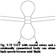
In the absence of a pilot the UAV designer has much more freedom. The contrarotating coaxial rotor is popular as it avoids the use of very small and delicate tail rotors. Figure 9.29 shows a typical UAV having coaxial rotors. The hull is axially symmetrical and high speed forward flight can be achieved by tilting the whole machine over. Tilt-rotor UAVs have also been developed.
Radio control is simply the use of radio signals to relay the position of control sticks without any physical connection. In practical applications there will be a need to have several control channels simultaneously available and each one will need to be proportional, which means that small or large movements of the control stick will be remotely reproduced by the movement of a servo.
The foundation of this technology was a patent by A. H. Reeves in the 1930s which showed that any type of information could be carried by varying the width or distribution of pulses. In a helicopter, the actual flying controls require four simultaneous
control channels. These will be lateral cyclic, fore-and-aft cyclic, collective and tail rotor. Subsidiary controls will be needed to start the engine and rotors and to adjust RRPM.
In an analog or pulse width modulation (PWM) system, each control is connected to a transducer such as a potentiometer or LVDT (see Chapter 7) that controls the length of a pulse. There will be one pulse for each control channel, followed by a reset or synchronizing pulse. The pulse signal is used to amplitude or frequency modulate a carrier wave in a radio transmitter. A receiver tuned to the transmitter will be able to demodulate the carrier signal and recover the pulse train. The reset pulse sets a pulse counter to zero. Each control pulse is then counted so that each pulse is routed to the correct channel.
A PWM system is analog because the infinitely variable position of a control stick results in an infinitely variable pulse length. In practical systems the resolution of the system may be reduced because of noise in the radio link. The digital or PCM (pulse code modulation) system converts the position of each control stick to a binary number of fixed word length. In an eight-bit system, there can be 256 different numbers. The binary numbers from the various control channels are multiplexed into a single transmission in which the number corresponding to each channel has a fixed place in the sequence. The start of the sequence is denoted by a fixed synchronizing pattern.


