Real-time conversion
Converting the batch simulations of the design phase to real-time code is often a disjointed process. Frequently, the MIL simulator has its own tightly integrated missile fly-out model. In some instances the same aerodynamic and autopilot subroutines are engaged in driving the aircraft and the missile, albeit with different data sets. The batch simulation is broken up and distributed over the subroutines of the combat simulator. You can imagine how difficult it is to validate the converted missile simulation. Many test cases have to be run in both environments, analyzed for inconsistencies and adjusted—only to have to execute the test cases again for revalidation.
Integrating the missile simulation as a complete entity streamlines the process, but sacrifices efficiency. CADAC provides a converter program that takes the batch simulation, strips it of unnecessary code, and translates it into a package that can be “dropped” into the MIL simulation. All missile subroutines remain intact, and only the interface variables have to be adjusted. Although this approach requires more code, execution speed remains essentially the same—a small price to pay considering the abundance of memory in modern computers. The rewards lie in the much simplified validation phase and the assurance that the missile model in the MIL simulator reflects accurately its performance.
|
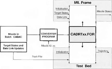
Fig. 11.11 CADAC converter program. |
The conversion takes place in several steps and applies equally to five – and six- DoF simulations. After having validated the missile simulation in the batch mode, the programmer runs a test case and records the input to the missile, e. g., target states, on a track file. Then the converter program translates the batch code into a subroutine package, which is validated in the test bed, driven by the track file. Now the code is ready for integration into the MIL frame simulator.
The schematic of Fig. 11.11 depicts this procedure. The missile identification code IDxx, inserted during conversion, attaches itself to every subroutine and labeled common statement. Thus, every missile package becomes unique, and different types of missiles can be flown in the MIL simulator simultaneously.
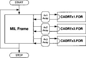
The communication between the MIL frame and the missile simulation occurs over a common A array. It is the exclusive conduit for missile initialization, target state tracking, and data link transmission, as well as the missile state feedback. Figure 11.12 shows the interface with three missile models, named xl, x2, and x3.
In summary, we reviewed air combat maneuvers and focused on the CIC engagement, stylized by the LAR-3 launch acceptable region, as the most demanding situation. Employing the five – and six-DoF simulations of a generic SRAAM, we assessed the effect of simulation fidelity on the pilot’s situation awareness. We concluded that five-DoF models, adjusted for six-DoF effects, could be used in CIC. They portray sufficiently accurate the time of flight and the firing zones for the pilot’s situation awareness. However, low-speed, close-in, and large off-boresight shots require six-DoF missile models, or, as a minimum, confirmation of such engagements by six-DoF batch runs. Integration of new missile concepts into combat simulators is greatly simplified by a conversion process that leaves the missile code intact, instead of overlaying it on the aircraft model.
|
Fig. 11.12 Interfaces between multiple missiles and MIL simulator. |


