Our heavyweight helicopter equal in the world does not have
In Rostov started production of the most load-lifting rotary-wing car The Russian holding «Helicopt[...]

Everything about aircrafts and helicopters. News and events in aviation worldwide. Civil, transportation, military helicopters and airplanes.

Everything about aircrafts and helicopters. News and events in aviation worldwide. Civil, transportation, military helicopters and airplanes.

Everything about aircrafts and helicopters. News and events in aviation worldwide. Civil, transportation, military helicopters and airplanes.

Everything about aircrafts and helicopters. News and events in aviation worldwide. Civil, transportation, military helicopters and airplanes.


Control of the helicopter in flight involves changing the magnitude of rotor thrust or its line of action or both. Almost the whole of the control task falls to the lot of the main rotor and it is on this that we concentrate. (The main rotor controls heave, surge/pitch, sway/roll, while yaw is controlled by a tail rotor or similar installation.) A change in line of action of the thrust would, in principle, be obtained by tilting the rotor shaft, or at least the hub, relative to the fuselage. Since the rotor is engine driven (unlike that of an autogyro), tilting the shaft is impracticable. It was attempted with the Cierva W9 as described in Chapter 1. Tilting the hub is possible with some designs but the large mechanical forces required restrict this method to very small helicopters. Use of the feathering mechanism, however, by which the pitch angle of the blades is varied, either collectively or cyclically, effectively transfers to the aerodynamic forces the work involved in changing the magnitude and direction of the rotor thrust.
Blade feathering, or pitch change, could be achieved in various ways. Thus Saunders [1] lists the use of aerodynamic servo tabs, auxiliary rotors, fluidically controlled jet flaps, or pitch links from a control gyro as possible methods.
The widely adopted method, however, is through a swashplate system, illustrated in Figure 4.14 (NFP is the No-Feathering Plane which is discussed later in the chapter.), which shows the operation with collective pitch, while Figure 4.15 shows the operation with cyclic pitch. Carried on the rotor shaft, this embodies two parallel star-shaped plates, the lower of which does not rotate (swashplate or non-rotating star) with the shaft but can be tilted in any direction by operation of the pilot’s cyclic control column and raised or lowered by means of the collective lever. The upper plate (spider or rotating star) is connected by control rods to the feathering hinge mechanisms of the blades and rotates with the shaft, while being constrained to remain parallel to the lower plate through a common bearing assembly. Raising the collective lever thus increases the pitch angle of the blades by the same amount all round (Figure 4.14), while tilting
Advancing
![]()
 |
Blade
Figure 4.15 Principles of the swashplate system (cyclic pitch)
the cyclic column applies a tilt to the plates and thence a cyclic pitch change to the blades (Figure 4.15), these being constrained to remain at constant pitch relative to the upper plate.
Figure 4.16 shows a typical control layout of a helicopter cockpit. It is an early design and is very simple. The aircraft is a Saunders Roe Skeeter, and while dual controls are provided, the pilot normally sits in the right-hand seat. More modern helicopters look more complicated with other system controls placed on the collective lever or cyclic stick, but are the same in essence.
An increase of collective pitch at constant engine speed increases the rotor thrust (short of stalling the blades), as for take-off and vertical control generally. A cyclic pitch change alters the line of action of the thrust, since the TPP of the blades, to which the thrust is effectively perpendicular, tilts in the direction of the swashplate angle.
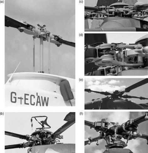
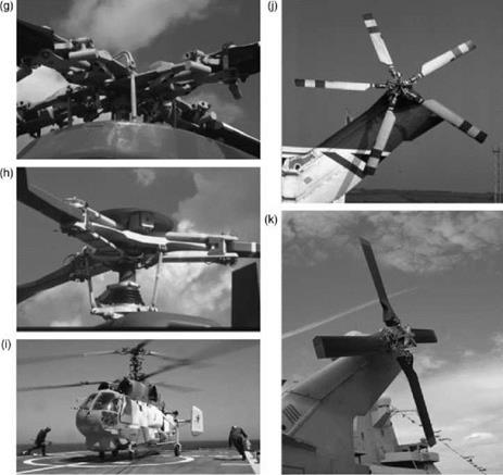
Rotor head designs vary considerably in detail as shown in Figures 4.17a-k. Figure 4.17a shows the simplest rotor head arrangement, namely the two-bladed teetering type. Figure 4.17b
shows a typical articulated rotor as used on the Sikorsky S61N. Figure 4.17c also shows a modern rotor of the fully articulated type. It is of an Agusta Westland Merlin and shows its location on top of the fuselage. Items discernible in the figure include the flap and lag elastomeric hinges, the feathering housing, the lag damper, the pitch control rods and the dual load path blade attachment.
Figure 4.17d shows a close-up view of a Merlin rotor head blade attachment and the blade restraint mechanism of the droop and anti-flap stops can be seen as a horizontal pin fitting into a slot. The main rotor blade folding mechanism is also shown. A good impression is gained of the mechanical complexity of this rotor head installation.
Figure 4.17e shows the semi-rigid rotor of the Westland WG30 (with vibration absorber fitted).
Figure 4.17f shows theMBB Bo 105 rotor head with pendulum vibration absorbers fitted to each blade attachment. The modern strap construction of the Bell 412 is shown in Figure 4.17g, which also has pendulum vibration absorbers installed.
Figure 4.17h shows the ‘Starflex’ rotor of the Eurocopter Ecureuil.
Figure 4.17i shows the complexity of a coaxial rotor system. The aircraft is the Kamov Helix and has two contra-rotating three-bladed rotors on the same shaft.
In comparison, the tail rotor of a Sikorsky S61NM is shown in Figure 4.17j while that of a Merlin is shown in Figure 4.17k.
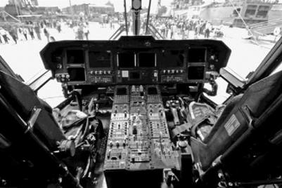
Figure 4.18 is an interior view of the cockpit of a modern helicopter (dual controls).
The collective pitch lever is down at seat level on the pilot’s left (right-hand seat); the cyclic control stick is directly in front between the knees. The foot pedals control the collective pitch of the tail rotor (normally its only control), the purpose of which is to balance the torque of the main rotor, or when required to change the heading of the aircraft.
Cyclic pitch on the main rotor implies a blade angle changing with azimuth, relative to the SNP. The once-per-cycle periodicity means that the pitch angle can be described mathematically by a negative Fourier series, in like manner to that used for the flapping angle.
We write:
![]()
 |
У = $o —A1 cos C-B sin ф—А2 cos 2ф—Б2 sin 2C •••
|
Figure 4.17 (a) Main rotor head of a Bell JetRanger helicopter. (b) Main rotor head of a Sikorsky S61N helicopter. (c) Agusta Westland Merlin main rotor head. (d) Agusta Westland Merlin main rotor head. (e) Semi-rigid main rotor head of a Westland WG30 helicopter. (f) Main rotor head of a Bolkow Bo105 helicopter. (g) Main rotor head of a Bell 412 helicopter. (h) Starflex main rotor head of a Eurocopter Ecureuil helicopter. (i) Coaxial rotor assembly for a Kamov Helix helicopter (Courtesy US Navy). (j) Tail rotor of a Sikorsky S61NM helicopter. (k) Tail rotor of an Agusta Westland Merlin helicopter. The mechanical connections between the rotor controls and blades differ between main and tail rotors. This is because they operate under different aerodynamic requirements. With a main rotor, the connections are aligned so that blade flapping does not influence the blade pitch angle. With a tail rotor, the control geometry is differently aligned to give a coupling between the blade flapping and pitching. This is sometimes referred to as a delta 3 hinge. |
|
Figure 4.17 (Continued) |
The physical design of a swashplate system only permits once per revolution changes in the pitch angle so only the constant and first harmonic terms are normally required:
в = в0— A1 cos ф—В1 sin C (4-9)
• The constant term в0 represents the collective pitch.
• The terms in C represent the cyclic pitch:
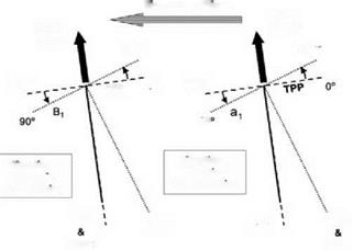
– The factor A1, which applies maximum pitch when the blades are at 0° and 180°, is referred to as the lateral cyclic coefficient because the rotor response, phased 90°, produces a control effect in the lateral sense.
– The factor B1 is the longitudinal cyclic coefficient.
The value of pitch angle would be different if a different reference plane were used. In any flight condition, there is always one plane relative to which the blade pitch remains constant with azimuth. This, by definition, is the plane of the swashplate, which is therefore known as the control plane or, referring to the elimination of cyclic pitch variation, the no-feathering plane
|
Figure 4.18 Cockpit of an Agusta Westland Merlin helicopter |
(NFP). NFP, though not fixed in the aircraft, is a useful adjustable datum for the measurement of aerodynamic characteristics considered in the next chapter.
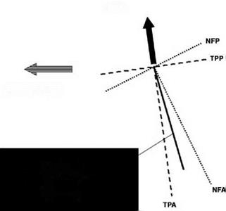
In some contexts it is useful to refer to the axes TPA and NFA, perpendicular to the TPP and NFP, rather than to the planes themselves. Generally in forward flight these two axes and also the shaft axis will be away from the vertical (i. e. the normal to the flight path). Figure 4.19
Rotor
Thrust
Direction of Flight
Shaft Axis
(determines attitude
of helicopter
fuselage)
 shows a common arrangement. The thrust line being inclined in the direction of flight, the TPP normal to it is tilted down at the nose relative to the horizontal (the flight direction). The TPA, being also the thrust line, is away from the vertical as shown. The shaft axis is tilted further from the vertical, the angle with the TPA being the tilt-back angle of the flapping motion. The inclination of the shaft axis to the NFA depends upon the degree of feathering in the helicopter motion.