Basic Equations
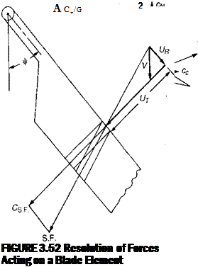
For this analysis, the procedure used in deriving the closed-form equations will be modified somewhat by resolving both the lift and drag forces into a normal—or thrust—force where before only lift was assumed to contribute to thrust. Figure 3.52 shows the forces on a blade element.
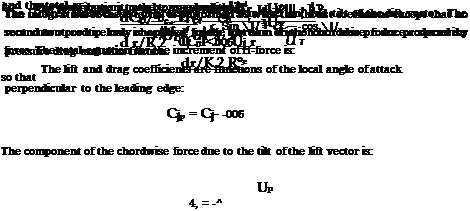
The normal force coefficient is:
The contribution of the entire blade is:

|
r *о0. + л„) „ „Ьв+Уіо) і————————– I[4] – щ——————— |
 |
|
The integration can be performed by any of several methods suitable for numerical analysis. One of the simplest is Simpson’s rule. If the blade is evenly divided into ten elements from the center of rotation to the tip, the integration uses the eleven points calculated at the margin of each element:
The total thrust coefficient is the average of CT/o evaluated at N equally spaced azimuth positions around the rotor:
1 N
CT/o = —^ ACT/o,
N tl=l
The number of azimuth stations required is a matter of compromise between accuracy and computer time which will have to be made to satisfy the particular needs of the analyzer. (Our experience indicates that for most rotor conditions in which retreating blade stall is not a factor, eight azimuth stations are sufficient for engineering accuracy.)
![]()
The equivalence of flapping and feathering allows performance calculations to be based on a rigid rotor whose tip path plane is perpendicular to the shaft and whose pitching and rolling moments are trimmed out with cyclic pitch. These calculations will then apply to any condition in which the thrust and the angle of attack of the tip path plane are the same. The normal force coefficients are used to produce the pitching and rolling moment coefficient loadings:
![]()
and
The integrations for the entire moments are carried out with the same method used for thrust.
The chordwise force that contributes to torque and H-force is made up of three components: those due to pressure drag, skin friction, and tilt of the lift vector. In the closed-form derivation, pressure drag and skin friction were treated as one, being assumed to be governed by the component of velocity perpendicular to the leading edge. This is strictly otily true for pressure drag. Skin friction is a function of the magnitude and direction of the total local velocity as shown in Figure 3.52. The skin friction force, S. F., is:
S. F. = % cAr(U2T+ U2R)cf
where
UR = fJL cos ф
|
‘S-F – s/U+ Ul 2 The chordwise coefficient is: |
|
= – cArUr?U2r+ U c, |
The chordwise component of S. F. is:
![]() UT^U2T+ u
UT^U2T+ u
![]() -cArU2B
-cArU2B
2
 |
The total chordwise coefficient due to both pressure drag and skin friction
0 = 0O + ^ 0j – Ax cos |/ – Bx sin |/
0Т = Г£ + l sin \i
— V f
Up = ^ ~ Tlr У cos ^ ” ^a°cos ^
Where the closed-form equations can be used with sufficient accuracy for a0 and for vJClR:
2 CT/a 2sR а°~ЬУ a ~ (ClR)2
vJClR — C-r/o _
(The value of CT/a is initially either known or can be estimated from the closed – form equations. The value will be updated after the first full cycle of calculations.)
For cases in which the rotor has prescribed pitching or rolling velocities, the equation for Up is modified by adding:
r 0 г Ф.
Af/’ = Yficosv + lTnsmy
In these cases, trim is the condition in which the rotor aerodynamic pitching and rolling moments are equal to the rotor gyroscopic moments instead of to zero as in steady flight conditions. The gyroscopic pitching moment reacted on the shaft of a round flat disc that has a rolling velocity, Ф, is:
іМя„=уФП
where J is the polar moment of inertia. For a single blade instead of a disc, the equation becomes:
iVf^ = 2/,Ф П
 |
|
and
The blade flapping moment of inertia can be related to the Lock number:
![]() cpaR4
cpaR4
Y
 |
||
Similarly
The rotor is in trim when:
^Лі/^ісго + См/Ggyro — 0 <
Ск/®ісго + ^fl/^gyro = 0
Since the sign and magnitude of a can vary widely over the rotor disc, it is necessary that the airfoil characteristics be defined throughout the entire range. Figure 3.53 shows the relationships between the angle of attack and the ratio of UP to UT. Also shown are the lift and drag coefficients of an NACA 0012 airfoil measured in a wind tunnel and reported in reference 3.32. When the airfoil characteristics are used as a function of a with the signs as shown, the normal and chordwise force equations will automatically resolve the lift and drag components into forces with the correct orientation. (Note: for the cases where UP and UT are both negative, the angle is in the third quadrant and computers will usually assign it a minus sign—for example, —135°. It is necessary in this procedure to add 360° so that the third quadrant angle is positive—for example, 225°.) The airfoil lift and drag coefficients can be written as equations that are a function of a, and the local Mach number, M, by the method outlined in Chapter 6. The local Mach number is:
![]() UBClR
UBClR
Speed of sound


