Our heavyweight helicopter equal in the world does not have
In Rostov started production of the most load-lifting rotary-wing car The Russian holding «Helicopt[...]

Everything about aircrafts and helicopters. News and events in aviation worldwide. Civil, transportation, military helicopters and airplanes.

Everything about aircrafts and helicopters. News and events in aviation worldwide. Civil, transportation, military helicopters and airplanes.

Everything about aircrafts and helicopters. News and events in aviation worldwide. Civil, transportation, military helicopters and airplanes.

Everything about aircrafts and helicopters. News and events in aviation worldwide. Civil, transportation, military helicopters and airplanes.


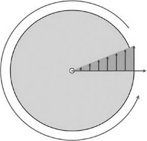
With reference to Figure 4.21, we have a circular disc on which is a radial direction rotating with it. The rotation will impart a velocity in a direction perpendicular to the radial direction (the tangential direction).
This velocity increases as the distance from the disc centre increases, so any point moving along the radial line (and remaining on that line) must acquire this increasing tangential velocity as it moves outwards from the disc centre. Obviously, if the movement is radially inwards towards the disc centre, this tangential velocity must decrease. We therefore have the situation where a rotating system causes a radial movement to acquire a velocity in a tangential direction which changes in magnitude – that is, an acceleration. This is the principle of the Coriolis acceleration.
Now, such acceleration will require the application of an appropriate force in the tangential direction. In many circumstances, such a force is not present and so the motion cannot remain on the line. In fact it will drift off in the opposite direction.
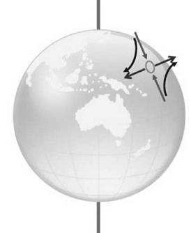
Coriolis can be found in many situations, one of which is the rotating winds found with depressions across the world.
Figure 4.22 shows the Earth with a region of low pressure whereby the air is moving towards it. The low pressure lies in the northern hemisphere and the inward movement of air in the direction towards the North Pole will be moving in towards the axis of the Earth’s rotation. This will be subject to the Coriolis effect and since there is no force, the air will move in an easterly direction. Conversely, a wind moving away from the North Pole will be subject to a movement
|
Figure 4.21 Rotating system |
|
|
|
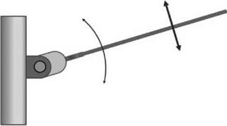
Figure 4.23 Blade flapping hinge |
in a westerly direction. In this way a rotating flow will be generated. This gives the characteristic anticlockwise rotation around a low-pressure region in the northern hemisphere with the opposite rotation direction found in the southern hemisphere.
Figure 4.23 shows the typical flapping motion of a rotor blade. The rotation of the blade about the flapping hinge gives any point of the blade a motion which is radially inwards and outwards, depending on the blade position and its flapping motion. In fact an analysis of this situation shows that the Coriolis effect is proportional to the product of the flapping angle and the flapping rate, that is:
Coriolis / bb (4-10)
The normal condition for a rotor is with the rotor in a coned position upon which flapping oscillations are superimposed. This means that the Coriolis effect will be more pronounced for a rotor with a high coning angle.
It can now be seen that the flapping motion of a rotor blade generates a distribution of Coriolis forces on the blade, along its length, which combine to give an overall moment about an axis parallel to the rotor shaft (see Figure 4.23).
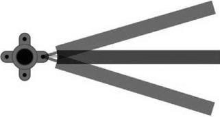
This will place a vibratory moment on the rotor hub structure which must be avoided. This can be achieved by allowing the blade to rotate in the rotor plane itself by installing a suitable hinge mechanism. This blade motion is termed lagging (Figure 4.24) and the instantaneous
|
|
|
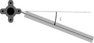
Figure 4.25 Definition of blade lag angle |
blade position away from directly outwards is called the lag angle (see Figure 4.25) and is usually given the symbol Z.