Our heavyweight helicopter equal in the world does not have
In Rostov started production of the most load-lifting rotary-wing car The Russian holding «Helicopt[...]

Everything about aircrafts and helicopters. News and events in aviation worldwide. Civil, transportation, military helicopters and airplanes.

Everything about aircrafts and helicopters. News and events in aviation worldwide. Civil, transportation, military helicopters and airplanes.

Everything about aircrafts and helicopters. News and events in aviation worldwide. Civil, transportation, military helicopters and airplanes.

Everything about aircrafts and helicopters. News and events in aviation worldwide. Civil, transportation, military helicopters and airplanes.


The wing shape chosen in Section 2.3.2 strives to maximize the wing area, and hence the lift, for a given dimension. However, the TiVs associated with the present low
 |
 |
Figure 2.43. Wing-shape geometry: (a) modified wing; (b) endplates’ location on the modified wing [155].
AR wing also substantially affect its aerodynamics. It is well established that the TiV causes a downwash that modifies the pressure distribution on the wing surface and increases the induced drag. Various methods to reduce the induced drag by decreasing the TiV effects are described in the literature and confirmed by actual applications to aircraft wing design [164]. Viieru et al. [155] reported the implications of placing endplates at the wingtip, which is simple from the manufacturing point of view.
Viieru et al. [165] investigated the effects of endplates on MAV rigid-wing aerodynamics. In that study they simply added the endplate to the existing MAV wing to probe its effect on the TiV and overall aerodynamics, while retaining the wing shape. They observed that the endplate increases lift by reducing the downwash and increases the effective AoA. However, drag increases along with the curved endplate in part because the endplate behaves as a vertically placed airfoil and the additional form drag causes the overall lift-to-drag ratio to decrease.
To remedy the disadvantages of the endplates, Viieru et al. [155] studied three alternative wing geometries: the original wing discussed at the beginning of this chapter, a modified wing (Fig. 2.43a) with a trimmed tip, and a modified wing with endplates (Fig. 2.43b). Compared with the original wing, the trimmed wing has a shorter span of 14 cm and a small wing area of 155 cm2, whereas the root chord is the same length as with the original wing. The endplate attached to the modified wing, which is parallel to the flight direction, has a length of 4.4 cm and a height of 3.4 cm.
One can observe the vortex intensity and the circulation by looking at the slices perpendicular to the streamwise direction behind the wing. Behind the trailing edge, the flow can be approximated with a vortex core of constant rotation and a potential motion outside the core. The relation between the pressure at the vortex center and the circulation around a rigid rotating body is given by [166]:
Г2 = 4n M^center/A (2-23)
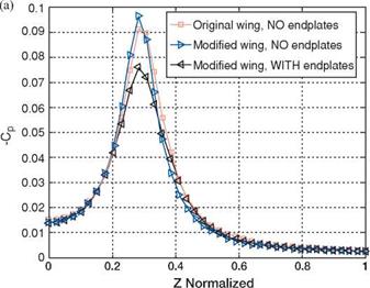
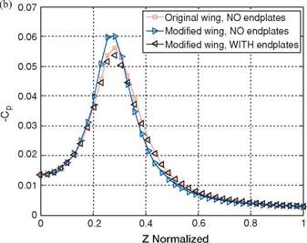
where r1 is the rigid body radius and Pcenter is the pressure at the rigid body center. Equation (2-23) shows that the vortex strength, measured by its circulation, is proportional with the pressure drop in the vortex core and its radius. In Figure 2.44, the pressure coefficient is plotted along the vortex core diameter at x/c = 3 behind the wing and x/c = 5. The amount of pressure drop inside the vortex core indicates
|
|
|
Figure 2.44. Pressure coefficient along the vortex core behind the wing at AoA = 6°: (a) x/c = 3; (b) x/c = 5 [155]. |
that the endplates reduce the vortex strength. Also, the modified wing without the endplates shows the strongest vortex.
From the pressure contours and horizontal velocity contours, one observes that the endplate affects the flow field over the wing. The endplate slows down the flow near the wingtip. This decrease in velocity reduces the pressure drop on the upper-wing surface corresponding to the vortex core (Fig. 2.45a). In contrast, a lower velocity slightly below the wing increases the high-pressure area there, because more momentum is transferred to the wing as pressure instead of being shed as vorticity at the wingtip. The increase in the high-pressure zone on the lower wing surface in the presence of the endplate can be clearly seen from the spanwise pressure coefficient on the lower-wing surface plot (Fig. 2.45b).
 |
Figure 2.46 plots the spanwise lift distribution obtained by integrating the pressure difference along the local chord at a specified spanwise location. It clearly shows that when the endplates are attached the lift on each cross-section is higher compared to the wing without the endplate. With a smaller overall wing area, the modified wing with the endplates produces almost the same lift as the original wing. Furthermore, the modified wings (with and without an endplate) experience lower drag over almost 75 percent of the wingspan starting from the root.
In Table 2.1 the overall aerodynamic performance parameters are presented for the AoA = 6°. The modified wing configuration with endplates has a better lift-to-drag ratio than the baseline configuration (10 percent improvement). This
Figure 2.46. tribution at drag [155].
![]()
![]()
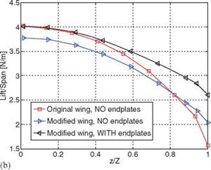
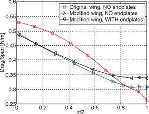 improvement is mainly due to the reduction in drag caused by the modified wing shape because the total lift is essentially the same. In Table 2.2 the same parameters are presented for the AoA = 15°. The modified wing with endplates shows an increase of 1.4 percent in lift-to-drag ratio compared with the baseline configuration.
|
Table 2.1. Aerodynamic forces at a 6° AoA
Source: [155]. |
|
Table 2.2. Aerodynamic forces at a 15° AoA
Source: [155]. |