
Our heavyweight helicopter equal in the world does not have
In Rostov started production of the most load-lifting rotary-wing car The Russian holding «Helicopt[...]

Everything about aircrafts and helicopters. News and events in aviation worldwide. Civil, transportation, military helicopters and airplanes.

Everything about aircrafts and helicopters. News and events in aviation worldwide. Civil, transportation, military helicopters and airplanes.

Everything about aircrafts and helicopters. News and events in aviation worldwide. Civil, transportation, military helicopters and airplanes.

Everything about aircrafts and helicopters. News and events in aviation worldwide. Civil, transportation, military helicopters and airplanes.


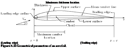
The geometrical section of a wing obtained by cutting it by a vertical plane parallel to the centerline of the aircraft is called aerofoil section. The lift generated and the stall characteristics of a wing strongly depends on the geometry of the aerofoil sections that make up the wing. The geometric parameters that dictate the aerodynamic characteristics of the aerofoil section are; the leading-edge radius, the mean camber line, the maximum thickness and the thickness distribution of the profile, and the trailing-edge angle. These parameters are shown in Figure 4.23.
4.16.1 Aerofoil Nomenclature
The tests made at Gottingen during World War I contributed significantly to the development of modern types of wing sections. Up to about World War II, most wing sections in common use were derived mostly from the work at Gottingen. During this period many families of wing sections were tested in the laboratories of various countries, but the work of the National Advisory Committee for Aeronautics (NACA)
 |
was outstanding. The NACA investigations were further refined by separation of the effects of camber and thickness distribution, and the experimental work was performed at higher Reynolds number than were generally obtained elsewhere. As a result, the geometry of many aerofoil sections is uniquely defined by the NACA designation for the aerofoil.
Aerofoil geometry are usually characterized by the coordinates of the upper and lower surface. It is often summarized by a few parameters such as: maximum thickness, maximum camber, position of max thickness, position of max camber, and nose radius (see Figure 4.23). One can generate a reasonable aerofoil section given these parameters. This was done by Eastman Jacobs in the early 1930s to create a family of aerofoils known as the NACA Sections. The NACA aerofoils are aerofoil shapes for aircraft wings developed by the National Advisory Committee for Aeronautics (NACA). The shape of the NACA aerofoils is described using a series of digits following the word “NACA.”
The NACA 4-digit and 5-digit aerofoils were created by superimposing a simple mean-line shape with a thickness distribution that was obtained by fitting a couple of popular aerofoils of the time:
у = ±(t/0.2) x (0.2969×0’5 – 0.126x – 0.3537×2 + 0.2843×3 – 0.1015×4).
The camber-line of 4-digit sections was defined as a parabola from the leading edge to the position of maximum camber, then another parabola back to the trailing edge, as illustrated in Figure 4.24.
Leading edge
c
Figure 4.24 Illustration of the camber line of a 4-digit NACA aerofoil.
NACA 4-Digit Series:
The first digit implies the maximum camber in percentage of chord (c), the second digit gives the position of maximum camber in 1/10 of chord, the last two digits give the maximum thickness in percentage of chord. For example:
1. NACA 4412 aerofoil has a maximum camber of 4% of chord, with the maximum camber located at
0. 4c and thickness-to-chord ratio 12%.
2. NACA 2412 aerofoil has a maximum camber of 2% located 40% (0.4c) from the leading edge with a maximum thickness of 12% of the chord. Four-digit series aerofoils by default have maximum thickness at 30% of the chord (0.3c) from the leading edge.
3. NACA 0015 aerofoil is symmetrical, the 00 indicating that it has no camber. The 15 indicates that the aerofoil has a 15% thickness to chord length ratio: it is 15% as thick as it is long.
After the 4-digit sections came the 5-digit sections such as the famous NACA 23012. These sections had the same thickness distribution, but used a camber-line with more curvature near the nose. A cubic was faired into a straight line for the 5-digit sections.
NACA 5-Digit Series:
In NACA 5-digit series the first digit gives approximate maximum camber in percentage of chord, the second and third digits give the position of maximum camber in 2/100 of chord and the last two digits give the maximum thickness in percentage of chord. This NACA 23012 is an aerofoil with maximum camber as 2% of c, position of maximum camber at 60% of chord and t/c = 0.12.
Four – and five-digit series aerofoils can be modified with a two-digit code preceded by a hyphen in the following sequence:
1. One digit describing the roundness of the leading edge with 0 being sharp, 6 being the same as the original aerofoil, and larger values indicating a more rounded leading edge.
2. One digit describing the distance of maximum thickness from the leading edge in tens of percentage of the chord.
For example, the NACA 1234-05 is a NACA 1234 aerofoil with a sharp leading edge and maximum thickness as 50% of the chord (0.5 chords) from the leading edge.
In addition, for a more precise description of the aerofoil all numbers can be presented as decimals.
1-series:
A new approach to aerofoil design pioneered in the 1930s in which the aerofoil shape was mathematically derived from the desired lift characteristics. Prior to this, aerofoil shapes were first created and then had their characteristics measured in a wind tunnel. The 1-series aerofoils are described by five digits in the following sequence:
1. The number “1” indicating the series.
2. One digit describing the distance of the minimum pressure area in tens of percent of chord.
3. A hyphen.
4. One digit describing the lift coefficient in tenths.
5. Two digits describing the maximum thickness in percentage of chord.
For example, the NACA 16-123 aerofoil has minimum pressure 60% of the chord back with a lift coefficient of 0.1 and maximum thickness of 23% of the chord.
The 6-series of NACA aerofoils departed from this simply-defined family. These sections were generated from a more or less prescribed pressure distribution and were meant to achieve some laminar flow.
NACA 6-Digit Series:
In NACA 6-digit series the first digit refers to the series, the second digit gives the location of minimum Cp in 1/10 chord, the third digit gives the half width of low drag bucket in 1/10 of CL, the fourth digit gives the ideal CL in tenths of CL, the fifth and sixth digits give the max thickness in percentage of chord.
An improvement over 1-series aerofoils with emphasis on maximizing laminar flow. The aerofoil is described using six digits in the following sequence:
1. The number “6” indicating the series.
2. One digit describing the distance of the minimum pressure area in tens of percentage of chord.
3. The subscript digit gives the range of lift coefficient in tenths above and below the design lift coefficient in which favorable pressure gradients exist on both surfaces.
4. A hyphen.
5. One digit describing the design lift coefficient in tenths.
6. Two digits describing the maximum thickness in tens of percentage of chord.
For example, the NACA 612-315 a = 0.5 has the area of minimum pressure 10% of the chord back, maintains low drag 0.2 above and below the lift coefficient of 0.3, has a maximum thickness of 15% of the chord, and maintains laminar flow over 50% of the chord.
After the six-series sections, aerofoil design became much more specialized for the particular application. Aerofoils with good transonic performance, good maximum lift capability, very thick sections and very low drag sections are now designed for each use. Often a wing design begins with the definition of several aerofoil sections and then the entire geometry is modified based on its 3-dimensional characteristics.
NACA 7-Digit Series:
Further advancement in maximizing laminar flow has been achieved by separately identifying the low pressure zones on upper and lower surfaces of the aerofoil. The aerofoil is described by seven digits in the following sequence:
1. The number “7” indicating the series.
2. One digit describing the distance of the minimum pressure area on the upper surface in tens of percentage of chord.
3. One digit describing the distance of the minimum pressure area on the lower surface in tens of percentage of chord.
4. One letter referring to a standard profile from the earlier NACA series.
5. One digit describing the lift coefficient in tenths.
6. Two digits describing the maximum thickness in tens of percentage of chord.
7. “a =” followed by a decimal number describing the fraction of chord over which laminar flow is maintained. a = 1 is the default if no value is given.
For example, the NACA 712A315 has the area of minimum pressure 10% of the chord back on the upper surface and 20% of the chord back on the lower surface, uses the standard “A” profile, has a lift coefficient of 0.3, and has a maximum thickness of 15% of the chord.
NACA 8-Digit Series:
Eight digit series profiles are supercritical aerofoils designed to independently maximize airflow above and below the wing. The numbering is identical to the 7-series aerofoils except that the sequence begins with an “8” to identify the series.
However, because of the rapid improvements in computer hardware and computer software, and because of the broad use of sophisticated numerical codes, we often encounter aerofoil sections being developed that are not described by the standard NACA geometries.


