
Our heavyweight helicopter equal in the world does not have
In Rostov started production of the most load-lifting rotary-wing car The Russian holding «Helicopt[...]

Everything about aircrafts and helicopters. News and events in aviation worldwide. Civil, transportation, military helicopters and airplanes.

Everything about aircrafts and helicopters. News and events in aviation worldwide. Civil, transportation, military helicopters and airplanes.

Everything about aircrafts and helicopters. News and events in aviation worldwide. Civil, transportation, military helicopters and airplanes.

Everything about aircrafts and helicopters. News and events in aviation worldwide. Civil, transportation, military helicopters and airplanes.


The preceding paragraphs have been devoted mainly to the sensor and its heat exchange with the fluid stream. The sensor must be controlled by an electronic circuit, which is a very important element of the anemometer. It provides a controlled electric current to the sensor and ensures the compensation of frequency. A sensor itself cannot follow speed variations at frequencies above 300 Hz; with electronic compensation this response may be increased to values of the order of kHz.
3.5.1 Schematic of a CCA
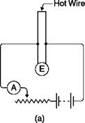
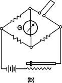
The current in the sensor is maintained essentially constant by using a large resistor in series with the sensor: since the current flowing in the circuit is I = E(R + R„), if R >> Rw, the current will be practically independent of Rw. In practice, a Wheatstone bridge (Figure 3.9 b) is used and the voltage drop across the sensor is measured by the unbalance of the bridge.
A physical point of view confirms the trend of E = E(U) of Figure 3.8: if the speed increases ^ heat transfer between the sensor and the fluid increases ^ the sensor cools down ^ its electrical resistance decreases ^ the potential difference across the resistor decreases (as the current through the sensor is constant). An amplifier picks up this change in voltage and then amplifies the signal to levels useful for recording.
Circuits of constant current anemometers
One of the limitations of the CCA is the fact that if too low an electric current is chosen, at the higher stream speeds the wire is too cold, its temperature tends to air temperature and the sensitivity of the anemometer decreases. Conversely, if too high an electric current is chosen, when the stream speed is too low, the danger of burning the wire exists: this is the case for measures in the boundary layer, where the velocity tends to zero, or in the case of removing the probe from the stream before shutting down the power supply to the wire.

