Our heavyweight helicopter equal in the world does not have
In Rostov started production of the most load-lifting rotary-wing car The Russian holding «Helicopt[...]

Everything about aircrafts and helicopters. News and events in aviation worldwide. Civil, transportation, military helicopters and airplanes.

Everything about aircrafts and helicopters. News and events in aviation worldwide. Civil, transportation, military helicopters and airplanes.

Everything about aircrafts and helicopters. News and events in aviation worldwide. Civil, transportation, military helicopters and airplanes.

Everything about aircrafts and helicopters. News and events in aviation worldwide. Civil, transportation, military helicopters and airplanes.


It is known that rotor devices in the form of rotating cylinders and rotating flaps attached to the main foil can be used as one of the possibilities to enhance and control the aerodynamic efficiency of lifting systems.
In connection with the importance of edge effects for the aerodynamic behavior of wings operating in the ground effect, rotor devices can be fitted on the leading, trailing and side edges to form rotating forward and rear flaps and rotating endplates.
In what follows, we discuss some simplified mathematical models of rotating devices fitted near the edges of a lifting surface in the ground effect. It is assumed, in particular, that when a rotating device is operating near a sharp edge, the Kutta-Zhukovsky type condition is satisfied at this edge at all times.
|
|
|
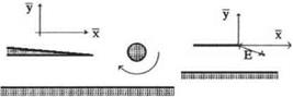
Fig. 6.13. A wing with a rotating flap at the trailing edge in the extreme ground effect. |
In the case of a rotating flap mounted in the vicinity of the trailing edge, this assumption implies that a supercirculation arises around the wing, which should eliminate large velocities induced at the trailing edge. It should be noted that the lift resulting from this supercirculation is much larger than a simple Magnus lift acting upon a rotating cylinder or a flap. The lift-to-drag ratio is significantly larger that for an isolated rotating flap due to a large chord to thickness ratio.
In the case of a rotor endplate, the mechanism of enhancing the lift is somewhat different. Here the requirement of finite velocities at the side edge of the wing (or tips of conventional endplates used for wing-in-ground-effect vehicles) slows down the leakage from under the side tips. Hence, we expect an increase in lifting capacity.
It should be noted that for both rotating flaps and rotating endplates, the resulting lift-to-drag ratio should be estimated accounting for the additional energy required for the rotation of the devices.
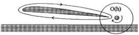
From the viewpoint of applying matched asymptotics techniques to the problem of flow past a wing-in-ground effect with rotating devices, the scheme of the solution should incorporate the analysis of the corresponding local flow in the vicinity of the wing tip with a rotor (rotating flap or rotating endplate); see Fig. 6.13.
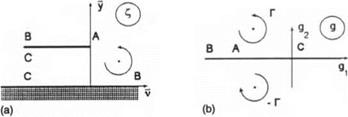
We turn to the derivation of the boundary condition for channel flow at the trailing edge with a rotating flap. Consider the case when the main lifting surface of a wing-in-ground-effect vehicle has a rear flap that can rotate around an axis located at its midchord. Replace the rotating flap by a vortex of circulation Г. In a local stretched trailing edge region, this vortex has a complex coordinate C7 = Щ + iy7, where v = — x see Fig. 6.14a.
We define the nondimensional circulation Г as
|
Fig. 6.14. (a) The stretched local region near the trailing edge with a rotating flap, (b) The auxiliary plane in the local problem of flow past a trailing edge with a rotating flap. |
where r0 is the nondimensional radius of an equivalent rotating cylinder equal to the semichord of a rotating flap, u> is the circular frequency of rotation, C0 is the chord of the main wing, U0 is the cruise speed of the vehicle, and к = uCq/Uq is the Strouhal number based on the chord. The local flow potential (p1 of the relative motion of the fluid can be sought in the form
<Pe = CLiifa + a2h(fb + IV7 + a3hv + a4.
The local flow near the trailing edge without a rotating flap was considered in section 2. Therefore, we have to determine only the additional term due to the rotor, that is, y?7. To solve for y?7, we map the flow field onto an auxiliary complex plane g = gi +i#2 shown in Fig. 6.14 b. This mapping is realized by the function
C=i(s + lnp + l). (6.143)
7Г
We find cp7 = 3?{F7(£)}, where the complex potential F7 of the vortex in the p-plane can be written as
F-y(9) = ^~In ^4^, (6.144) 2тгг g – 4 7
where g is the complex conjugate with respect to g. The complex coordinate g~, of the vortex in an auxiliary plane can be found from the equation
<7 = -($7 + In +1). (6.145)
7Г
Assume further that the rotation of the flap results in supercirculation around the wing. The magnitude and direction of this supercirculation is governed by the Kutta-Zhukovsky condition at the trailing edge. With this in mind, after complementing the right-hand side of (6.144) with a supercirculation term, we obtain
F-y(g) = ^- In ^ + <?7 Inp.
2тг г g g*y
Accepting the previously mentioned mechanism of the operation of a rotating flap, we find the constant C7 from the condition of no flow across the trailing edge of the main wing. Accounting for violation of the conformity of the mapping at point g = — 1 (image of the trailing edge), we can satisfy the Kutta-Zhukovsky condition by requiring that for g — —1,
![]()
![]() Щ = i_ + + = 0
Щ = i_ + + = 0
dg 2тг ig-g^ g-gy) g
wherefrom
7 2іті V -1 – gly – ig2j -1 – giy + іg2j
|
|
|
|
|
|
We consider the outer asymptotics of the flow velocity due to the rotor at some distance from the trailing edge along the upper and the lower surfaces of the lifting surface. We calculate the complex velocity in the physical plane
|
dF~ di+ dg ~dC~ = ~d*TdC |
|
|
![]()
On the surface of the wing in the vicinity of the trailing edge, we have to replace g with gi, so that
![]() dFy = dFy =______________________________ ,
dFy = dFy =______________________________ ,
dC dP [(gi -Зі7)2 +З27К1 +5i) l+5i
The upper surface asymptotics follows for g —» —00:
![]()
£ = u + i= — (5i + І7Г + In Iflri I + 1), i/~ — +0(1). (6.152)
7Г 7Г
It follows from (6.151), (6.152) that for V —00, у = 1 + 0 (gi —> —00, g2 = 0 + 0), the flow velocity behaves as
![]()
We turn to consideration of the outer asymptotics of the local flow velocity on the lower surface of the wing inside the channel, i. e., when g -» 0 — 0. In this case we can obtain from the expression for the mapping function
-(1 +І7Г + 1п|с/і|),
7Г
wherefrom
0i ra-exp(7rp), (6.155)
so that far upstream in the channel, g vanishes exponentially. Hence
Accounting for the obvious relationships v = —x = —x/h, dp1/dv = —hdp1/dx, we can represent the contribution of to the channel flow boundary condition at the trailing edge as
![]() = _I^7 =
= _I^7 =
дй h дй h 7
The corresponding boundary condition for the velocity of the relative motion of the fluid accounting for the structure of the local flow potential <pe can be written as follows:
where
In the previous expression, f0 = r0/h is an equivalent radius of a rotating flap (identical to a half-chord of the flap) related to the ground clearance and kro = uC0r0/U0 is the ratio of the flap edge linear velocity to the characteristic flow velocity U0. The parameter kro can be interpreted as a Strouhal number based on the radius of an equivalent rotating cylinder. Formula (6.158) should be used instead of formula (4.67) of section 4 as a channel flow boundary value of the spanwise-averaged velocity at a point x = 0, when solving flow equation (4.66) for a wing with a rotating flap. Observing that the structure of the flow problem (hence the structure of its solution) for the rotating flap is identical to that of a traditional rigid flap, we can interpret the quantity Sr,
5r = 1 + rf1{x1, y7), f1 = ^ g2 ’ (6.160)
as a relative effective gap behind the rotating flap. For example, for a wing with zero pitch angle, a rotating flap at the trailing edge, and nonzero clearances under the endplates, we can determine the lift and moment and induced drag coefficients by formulas (4.71), (4.72), and (4.74), replacing Sf with 6r given by expression (6.160). It is easy to see from (6.160) that to diminish the effective gap 5r, that is, to increase the lift, the flap should be rotated in the clock-wise direction (Г < 0).