
Our heavyweight helicopter equal in the world does not have
In Rostov started production of the most load-lifting rotary-wing car The Russian holding «Helicopt[...]

Everything about aircrafts and helicopters. News and events in aviation worldwide. Civil, transportation, military helicopters and airplanes.

Everything about aircrafts and helicopters. News and events in aviation worldwide. Civil, transportation, military helicopters and airplanes.

Everything about aircrafts and helicopters. News and events in aviation worldwide. Civil, transportation, military helicopters and airplanes.

Everything about aircrafts and helicopters. News and events in aviation worldwide. Civil, transportation, military helicopters and airplanes.


The swash plate concept was introduced in Chapter 2 (Fig. 2.5) as one of the key innovations in helicopter development, allowing one-per-rev variations in rotor blade pitch to be input in a quasi-steady manner from the actuators. The approximately 90° phase shift between cyclic pitch and the cyclic flapping response comes as a result of forcing the rotor with lift changes at resonance. In practice, cyclic pitch can be applied through a variety of mechanisms; the conventional swash plate is by far the most common, but Kaman helicopters incorporate aerodynamic surfaces in the form of trailing edge flaps and cyclic control in the Westland Lynx is effected through the so-called ‘dangleberry’, with the blade control rods running inside the rotor shaft. Whatever the physical mechanism, cyclic pitch requires very little energy to apply at one-per-rev, and, for our purposes, a generalized swash plate is considered, with a minimum of three actuators to provide the capability of tilting the swash plate at an arbitrary angle relative to the rotor shaft.
|
||
|
||
|
||
|
||
|
||
|
||
|
![]()
to pitch channel
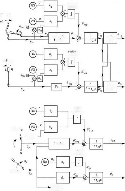
Fig. 3.36 Schematic of helicopter flight control system
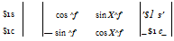
Progressing downwards along the control rods (assumed rigid) from the blades, and through the rotating swash plate, we come to the so-called mixing unit. This combines the actuation outputs from the two cyclic controls with a phase angle. For articulated and hingeless rotor configurations, even in the hover, the phase lag between cyclic pitch and flap is less than 90° and, to achieve a pure pitch or roll control, the pilot needs to apply a coupled input. As the forward speed increases, the response coupling changes due to the increased aerodynamic damping effects. A single mixing is usually selected as a compromise between these different conditions and can be written in the form
 (3.279)
where tyf is the mixing angle, usually between 8° and 12°, and a prime simply denotes the cyclic angle before mixing.
The next stage in the reverse sequence is the actuation itself. Most modern helicopters incorporate powered flying controls through hydraulic actuation. The actuation system is quite a complicated mechanism with its own feedback control designed to ensure that the response and stability to control inputs has good performance and stability characteristics. The actuation system has inherent nonlinearities at both small and large amplitudes, including rate limiting when the pilot demands more than the hydraulic system can supply. Typical rate limits are of the order 100% of full actuator range per second. Helicopters fitted with an AFCS usually incorporate a limited authority series actuation system driven by the voltage outputs of the SCAS element. As shown in Fig. 3.36, these augmentation inputs to the actuators are limited to amplitudes of the order ±10% of the full actuator throw. For our purposes we assume that each actuation element can be represented by a first-order lag, although it has to be recognized that this is a crude approximation to the complex behaviour of a complcated servo-elastic system; hence, we write the cyclic actuator outputs as the sum of pilot (subscript p) and AFCS (subscript a) inputs in the transfer function form
|
$ 1s p + $ 1sa 1s 1 + Tc1s |
(3.280) |
|
! $ 1c + $ 1c 77 1cp 1ca $ 1c — ч 1 + Tc2s |
(3.281) |
|
The time constants Tc1 and Tc2 are typically between 25 and 100 ms, giving actuation bandwidths between 40 and 10 rad/s. For systems operating at the lower end of this |
bandwidth range, we can expect the actuation to inhibit rapid control action by the pilot.
The mechanical control runs connect the actuators to the pilot’s cyclic stick through a series of levers and pulleys. At the stick itself, an artificial feel system is usually incorporated to provide the pilot with stick centring tactile cues. A simple spring with a breakout force is the most common form of feel system found in helicopters, with a constant spring gradient, independent of flight condition or manoeuvre state. If we neglect the dynamics of these elements, then the relationship for roll and pitch cyclic can be written in the simple algebraic form as
$1 Cp — g1co + g1ci mc + (gcco + gcci Vic)Vc (3.283)
where the g coefficients are the gains and offsets, and nic and nis are the pilot’s cyclic stick inputs. Included in the above equations are simple interlinks between the collective and cyclic, so that a collective input from the pilot also drives the cyclic control runs. In this way, collective to roll and pitch couplings can be minimized. The coefficients in eqns 3.282-3.283 can conveniently be expressed in terms of four parameters:
61s0 – the pitch at zero cyclic stick and zero collective lever V1si – the pitch at maximum cyclic stick and zero collective lever $1s2 – he pitch at zero cyclic stick and maximum collective lever 6iS3 – the pitch at maximum cyclic stick and maximum collective lever
The coefficients can therefore be written as
g1so — $1so g1s1 — &1s1 — $1s0 g1co — $1s2 — $1S1
g1c1 — ($1s3 – &1s2) – ($1s1 – 01so) (3.284)
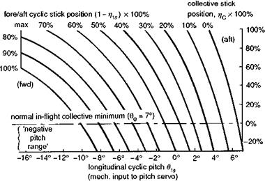
This analysis assumes a linear relationship between control movement and actuator input. In practice, the mechanical system will exhibit some nonlinearities particularly at the extremities of control throw due to the geometry of the linkage, and look-up tables will be a more appropriate representation. For example, Fig. 3.37 illustrates the cyclic/collective interlink functionality for the Lynx helicopter (Ref. 3.54).
With regard to the autostabilizer inputs, these will, in general, be complex functions of sensor and control inputs with various filters arranged to stabilize the feedback
|
Fig. 3.37 Geometry of mechanical interlink between collective and cyclic for Lynx (Ref. 3.54) |
dynamics and protect against sensor noise. For the present purposes we shall assume that the autostabilizer adds feedback control signals proportional to attitude and angular rate, together with a feedforward signal proportional to the pilot’s control input, referred to some adjustable datum (Fig. 3.36). This allows the zero or mid-range of the autostabilizer to be reset by the pilot during flight. This would be necessary, for example, if the attitude gains were high enough to cause saturation as the speed increases from hover to high speed. Other systems automatically disengage the attitude stabilization when the pilot moves his control, thus obviating the need for a pilot-adjustable zero (e. g., Puma). The simple proportional autostabilizer can be described by the equations
Oisa = keO + kqq + kis (nis – nis0) (3.285)
Oica = kфф + kpp + kic (nic – nic0) (3.286)
In Chapter 4, we shall demonstrate how rate stabilization alone is typically inadequate for stabilizing a helicopter’s unstable pitch motion. However, with a combination of fairly modest values of rate and attitude gains, k (O (0.i)), a helicopter can be stabilized throughout its OFE, and a pilot can fly ‘hands off’ or at least with some divided attention, hence allowing certification in IFR conditions. However, a low-authority AFCS will quickly saturate in aggressive manoeuvres, or during flight in moderate to severe turbulence, and can be regarded only as an aid to steady flight.
Yaw control
In a similar way, the pilot and autostabilizer commands are input to the yaw actuator servo in the simplified first-order transfer function form
The gearing between the actuator input and the yaw control run variable, ncT, can be written as
e0Tp = gTo + gTi ncT (3.288)
where the control run is generally proportional to both pedal, np, and collective lever, nc, inputs, in the form
ncj = gcT0(i – np) + Iі – 2gcTo) nc (3.289)
In eqn 3.289, the collective lever accounts for the normal mechanical interlink between collective and yaw to reduce yaw excursions following power inputs. Equation 3.289 is a linear approximation to a relationship that can become strongly nonlinear at the extremes of the control range, when the interlink geometry reduces the sensitivity. Figure 3.38 illustrates the nonlinear variation for the Lynx helicopter (Ref. 3.54).
Heave control
Finally, the main rotor collective pitch output from the main rotor servos, achieved through raising and lowering the swash plate, can be written in terms of the mechanical
and electrical inputs from the pilot and autostabilizer respectively, namely
![]()
![]()
 |
– 0 0p + 0 0a
0 0 = T1—————-
1 + Tc4s
The gearing with the collective lever is written as
°0p = gc0 + gc1 Пс
For most modern helicopters, there is no autostabilizer component in the collective channel, but for completeness we include here a simple model of the so-called collective acceleration control (Ref. 3.55) found in the Lynx. An error signal proportional to the normal acceleration is fed back to the collective, i. e.,
00a = kgaz (3.292)
For the Lynx, this system was implemented to provide dissimilar redundancy in the SCAS. At high speeds, the collective is a very effective pitch control on hingeless rotor helicopters, and this additional loop supplements the cyclic stabilization of aircraft pitch attitude and rate.
 Без верификации!")