Leading-Edge Vortices (LEVs)
When an airfoil is accelerated impulsively to a constant velocity, the bound vortex needs time to develop to its final, steady-state strength. Depending on the pace of acceleration, it may take up to six chord lengths of travel for the circulation and lift to reach 90 percent of the final values [213]. This lift enhancement can be explained in part by the so-called Wagner effect [274], which describes the unsteady aerodynamics associated with an accelerating airfoil. Specifically, an impulsively started airfoil only develops a fraction of its steady-state circulation immediately; the steady-state value can be attained only after the airfoil moves through several chord lengths. However, if the airfoil is started at an AoA above its stalling angle, then a large transient vortex forms above the leading edge, which can dramatically increase the lift [51]. Dickinson and Gotz [275] measured the aerodynamic forces of an airfoil impulsively started at a high AoA in the Reynolds number range of a fruit fly (Re = 75-225). They
observed that, at AoAs above 13.5°, impulsive movement resulted in the production of an LEV that stayed attached to the wing for the first two chord lengths of travel, resulting in an 80 percent increase in lift compared with the performance measured five chord lengths later. For a Reynolds number of 6.0 x 10⁴, Beckwith and Babinsky [276] experimentally investigated the relative importance of delayed stall and the Wagner effect for an impulsively started flat plate (AR = 4). They showed that the prestall plate shows a gradual build in lift force similar to Wagner’s prediction [274] and that the lift on the poststall plate rises more quickly to levels above steady state, which is a clear example of delayed stall. Force curves presented by Beckwith and Babinsky [276] are similar to those seen by Dickinson and Gotz [275] at Re < 1.0 x 10³, which implies that the Wagner’s effect on lift-force generation is less sensitive to the Reynolds number variation.
Most of the research on the dynamic-stall phenomenon has been performed on pitching airfoils. This 2D motion has been useful in highlighting the characteristics of dynamic stall on helicopter blades, fish swimming, and flapping flight. The viscous effects play an important role in these cases. This has led to a more careful investigation of the dynamic-stall process, including evaluation of the type of motion [246] involved (see Fig. 3.8). McCroskey et al. [277] showed the sensitivity to history effects in dynamic stall. They observed that the high-angle part of the oscillating airfoil in a dynamic-stall cycle depends significantly on the rate of change of the AoA near the stall angle; the same lift – and pitching-moment behavior can be attained by matching the rate of change of the AoA at stall limit with different amplitudes.
The potential benefit of trapped or wing-attached vortices in flapping-wing lift enhancement has long been recognized [43] [275] [278]-[280]. In particular, the high-lift mechanism generated by the LEV in a flying insect, which has received substantial attention, was first discovered by Ellington et al. [199]. It appears that the LEV can enhance lift by attaching the bounded vortex core to the upper leading edge during wing translation [199] [281]. The LEVs generate a lower pressure area in the suction side of the wing, which results in a large suction on the upper surface. It seems that the lift enhancement can be sustained for three or four chord lengths of travel before vortex breakdown or complete de-attachment occurs.
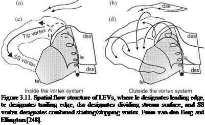
As previously discussed, Ellington and co-workers [199] [248] designed a 10:1 scaled-up robotic model for studying the aerodynamics of the hawkmoth Man – duca sexta (see Fig. 3.11). To maintain both the Reynolds number and the reduced frequency similarity in hovering, as introduced in Section 3.2, they preserve fR2 between the real insect and the mechanical model. The use of geometrically similar hawkmoth wing models that undergo hovering with the same flapping kinematics can therefore satisfy the aerodynamic similarity. By using smoke streams to visualize the flow around a flapping wing, Ellington et al. [199] demonstrated the presence of a vortex close to the leading edge of the hawkmoth wing model. They observed a small but strong LEV that persists through each half-stroke (downstroke). From these observations, they proposed that the LEV is responsible for enhancing lift- force generation. Furthermore, the LEV has a high axial flow velocity in the core and is stable, separating somewhat from the wing at approximately 75 percent of the wing length spanwise and then connecting to a large, tangled tip vortex. The overall vortical structures are qualitatively similar to those of low AR delta wings [199] that
 |
stabilize the LEV due to the spanwise pressure gradient, increasing lift well above the critical AoA. They further suggested that the LEV stability in flapping wings is maintained by a spanwise axial flow along the vortex core (see [199]) that creates “delayed stall,” thereby enhancing lift during the translational phase of the flapping motion.
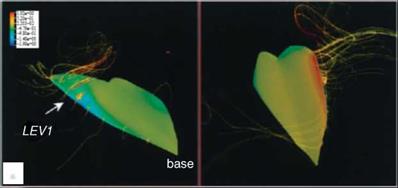
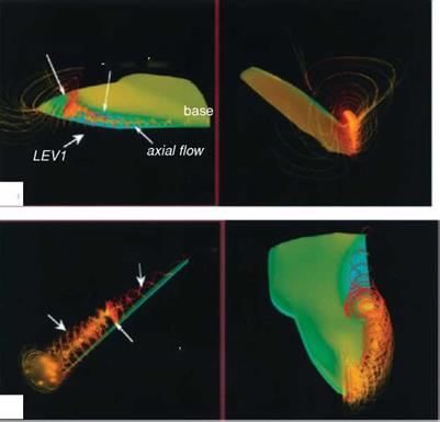
Using the same wing model and kinematics considered in Ellington et al [199], Liu and Kawachi [200] and Liu et al. [247] conducted unsteady Navier-Stokes simulations of the flow around a wing of hawkmoth Manduca sexta to probe the unsteady aerodynamics of hovering flight. They demonstrated the salient features of the LEV as well as the spiral axial flow during translational motions. Their results are consistent with those observed by Ellington et al. [199]. Figure 3.12 shows that the LEV created during previous translational motion and the vortical flows established during the rotational motions of pronation and supination together form a complex flow structure around the wing. The computed lift history shows that the lift is produced mainly during the downstroke and in the latter half of the upstroke.
Birch and Dickinson [254] investigated the LEV features of the flapping model fruit fly wing at the Reynolds number of 1.6 x 10². They reported that, in contrast to the LEV on the model hawkmoth wing, which detaches from the wing surface at approximately 75 percent of the wing length with the presence of a strong axial flow in the core, the LEV of the fruit fly exhibits a stable vortex structure without de-attachment during most of the translational phases. Furthermore, little axial flow is observed in the vortex core, amounting to only 2-5 percent of the averaged tip velocity [254]. However, strong spanwise flow is seen at the rear two-thirds of the chord, at about 40 percent of the wingtip velocity. For a fruit fly, the LEV is stably

 LEV2
LEV2
reverse point
#
(c)
During downstroke
Figure 3.12. Wing surface pressure and streamlines revealing the vortical structures from a 3D numerical simulation of a hovering hawkmoth [247]. (a) Positional angle ф = 30°; (b) ф = 0°; (c) ф = -36°. Reynolds number is approximately 4.0 x 10³ and the reduced frequency is 0.37.
attached throughout the half-stroke without breaking up. Based on these considerable differences between fruit fly and hawkmoth models, Birch and Dickinson [254] hypothesized that the attenuating effect of the downwash induced by the tip vortex and wake vorticity limits the growth of the LEV by lowering the effective AoA and prolonging the attachment of the LEV. Recently, using the time-resolved scanning tomography PIV technique David et al. [282] reported that, in the case of a translating
NACA 0012 wing with the AoA of 45° at Re of 1.0 x 10³, the tip downwash that originates from the formation of TiV indeed reduces the effective AoA and hence also the spanwise vorticity production at the leading edge. However, it should be noted that a NACA 0012 wing is relatively thicker than the model hawkmoth and fruit fly wing.
Another study [256] on large red admiral butterflies, Vanessa Atlanta, questioned the existence of axial flow even at the level of the Reynolds numbers comparable to that of hawkmoths. Using smoke trails to visualize the wake behind free-flying butterflies in a wind tunnel, the investigators showed that the LEV spreads from the wing surface to the body of the animal. In contrast to the conical LEV observed in the hawkmoth, the butterfly LEV exhibits a more cylindrical-shaped vortex with constant diameter, and at the end it connects with the tip vortex. Because the helical structure of the LEV is much weaker on a butterfly wing, the general role of axial flow for stabilizing the LEV was again questioned.
Thomas et al. [258] showed that dragonflies attain lift by generating high-lift LEVs using free – and tethered-flight flow visualization. Specifically, in normal free flight, dragonflies use counter stroke kinematics with an LEV on the forewing down- stroke and with attached flow on the forewing upstroke and on the hindwing throughout. When the dragonflies accelerate, they switch their kinematics to in-phase wing beats with highly separated downstroke flows, with a single LEV attached across both the fore – and hindwings. Based on their flow visualizations, Thomas and coworkers also suggested that the spanwise flow is not a dominant feature of the flow field. They observed that the spanwise flow sometimes runs from the wingtip only to the centerline, or vice versa, depending on the degree of sideslip. The LEV formation always coincided with the rapid increases in AoA. Furthermore, they reckoned that the flow fields produced by dragonflies differ qualitatively from those published for mechanical models of dragonflies, fruit flies, and hawkmoths, which preclude natural wing interactions. However, parametric assessment showed that, provided the Strouhal number is appropriate and the natural interaction between left and right wings can occur, even a simple plunging plate can reproduce the detailed features of the flow seen in dragonflies. Thomas et al. [258] suggested that stability of the LEV is achieved by a general mechanism whereby the flapping kinematics is configured such that an LEV would be expected to form naturally over the wing and remain attached for the duration of the stroke.
Birch et al. [283] conducted flow visualization around a robotic fruit fly model wing and also noticed that, although the LEV remains stable at both lower (Rep = 1.2 x 10²) and higher (Rep = 1.4 x 10³) Reynolds numbers, the flow changes from a relatively simple pattern at lower Reynolds numbers to spiral flow at higher Reynolds numbers. Vorticity measurements taken at mid-stroke, in a plane located at 0.65 of the wing length and perpendicular to the spanwise direction, show stronger and larger LEVs for the higher Reynolds numbers associated with intense axial (spanwise) velocity within the LEV core, with magnitudes significantly larger than those of the tip velocity [254]. At a lower Reynolds number, they observed no peak in axial flow in the area of the LEV core, likely because of the stronger viscous effect.
Kim and Gharib [284] experimentally studied spanwise flow generated by a flat plate by rotating and translating motions with a constant AoA of 45° at a Re of 1.1 x 10³. They observed that, for the translating plate, an LEV develops nonuniformly along the span because of the influence of the wingtip. This deformed LEV induces the spanwise flow over the flat plate and subsequent vorticity transport. However, the spanwise flow is not strong enough to suppress the growth of the LEV near the central region of the plate. For the rotation mode, the vorticity of the LEV is tilted because the size of the LEV increases from the base to the tip. The tilted vorticity induces the spanwise flow over the rotating plate. Contrary to the translation mode, the spanwise flow is also found in the wake; this spanwise flow is due to the streamwise component of vorticity, which is distributed inside a shear layer and a starting vortex in the wake.
The LEV of a flapping wing resembles that of a fixed delta wing. The delta wing owes much of the lift that it is able to generate to the fact that the vortex flow initiates at the leading edge of the wing and rolls into a large vortex over the leeward side, containing a substantial axial velocity component. This high-flow velocity in the core of the vortex is a region of low pressure that generates a suction (i. e., lift). For a delta wing placed at high AoAs, vortex breakdown occurs, causing the destruction of the tight and coherent vortex. The diameter of the core increases, and the axial velocity component is no longer unidirectional. With the loss of axial velocity the pressure increases, and consequently, the wing loses lift. The literature on the subject is immense, and for a more general presentation of the various aspects of vortex breakdown, we refer the reader to several review articles [164] [285] [286]. For a fixed wing, an important trend is that, at a fixed AoA, if the swirl is strengthened, then vortex breakdown occurs at lower Reynolds numbers. In contrast, a weaker swirling flow tends to break down at a higher Reynolds number. Since the fruit fly exhibits a weaker LEV, from this viewpoint, it tends to better maintain the vortex structure than a hawkmoth, which creates a stronger LEV.
Of course, the link between the vortex breakdown and a fixed or flapping wing, if any, is not established. It should be noted that, although helicopter blade models have been used to help explain flapping-wing aerodynamics, spanwise axial flows are generally thought to play a minor role in influencing helicopter aerodynamics [287]. In particular, helicopter blades operate at substantially higher Reynolds numbers and lower AoA. The much higher AR of a blade also makes the LEV harder to anchor.


