Rotor reference planes – hub, tip path and no-feathering
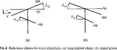
In rotor dynamics analysis, three natural reference axes systems have found application in various texts and reports – the hub (or shaft) system, the tip-path plane (or noflapping) system and the no-feathering system. These are illustrated in Fig. 3A.4, where the hub plane has been drawn horizontal for convenience. In this book we consistently use the hub system but it is useful to compare expressions for key rotor quantities in the three systems. The motivation for adopting the rotor-oriented no-flapping or nofeathering systems is that they greatly simplify the expressions for the rotor X and Y forces, as shown in Ref. 3A.1 The no-feathering axes are equivalent to the, so-called, control axes when the rotor pitch/flap coupling is zero. The control axis is aligned along the swash plate.
Assuming small angles, the normalized velocities in the rotor systems are related to those in the hub system by the approximate relationships
Htp — Hh + Hzh p1 Hztp = Hzh – Hh p1
Fig.
 and
and
pnf — ph №zh @1s
pznf — pzh + №h 8s (3A.58)
Similarly, the disc incidences are given by the expressions
atp — ah Pic
anf — ah + 6is (3A.59)
and the non-rotating rotor forces are given as
Xnf — Xh – T 9is
Xtp — Xh + T Pic (3A-60)
Ytp — Yh – TPis
Ynf — Yh – T9ic (3A.61)
where it is assumed that the rotor thrust T and Z forces in the three systems have the same magnitude and opposite directions.
In hover, the alignment of the tip-path plane and the no-feathering plane highlights the equivalence of flapping and feathering. These expressions are valid only for rotors with flap articulation at the centre of rotation. Elastic motion of hingeless rotors and flapping of articulated rotors with offset flap hinges cannot be described with these rotor axes systems. It should also be noted that the induced inflow discussed earlier in this chapter, X, is strictly referred to the tip-path plane, giving the inflow normal to the hub plane as
Xh — Xtp – p-Pic (3A.62)
This effect is taken into account in the derivation of the rotor torque given in this chapter (eqn 3.116), but not in the iterative calculation of X. The small flap angle approximation will give negligible errors for trim flight, but could be more significant during manoeuvres when the flapping angles are large.

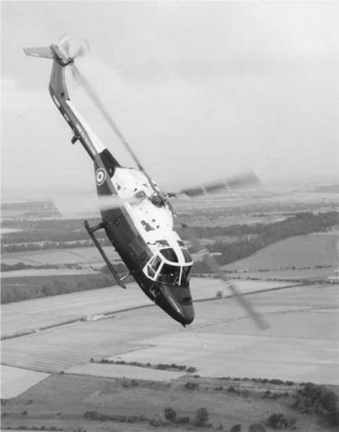
The Empire Test Pilot School’s Lynx in an agile pitch manoeuvre complementary to the cover picture (Photograph courtesy of DTEO Boscombe Down and the Controller HMSO)


