Our heavyweight helicopter equal in the world does not have
In Rostov started production of the most load-lifting rotary-wing car The Russian holding «Helicopt[...]

Everything about aircrafts and helicopters. News and events in aviation worldwide. Civil, transportation, military helicopters and airplanes.

Everything about aircrafts and helicopters. News and events in aviation worldwide. Civil, transportation, military helicopters and airplanes.

Everything about aircrafts and helicopters. News and events in aviation worldwide. Civil, transportation, military helicopters and airplanes.

Everything about aircrafts and helicopters. News and events in aviation worldwide. Civil, transportation, military helicopters and airplanes.


That symmetrical wing sections would have a fixed centre of pressure at the quarter chord point, so long as the airflow did not separate, was predicted by theory long before wind tunnel engineers discovered it to be so in practice. The same theory also gave special significance to the 25% chord point for cambered profiles. It was calculated that in the wind tunnel (with a constant speed of flow regardless of the angle of attack), even though the lift and drag forces varied as the angle of attack changed, if the pitching moment was always measured at the 25% point, it would remain constant. This was very easily tested in the wind tunnel and it was soon proved to be correct, or so nearly so that it could be assumed true for all practical engineering purposes. Wind tunnel results at the present time are obtained by measuring all the forces on the wing at the 25% point. Lift and drag forces are reduced to coefficient form, using the equations given in Chapter 2 (2.6 & 2.13). The pitching force is treated in exactly the same way. The result is that although the lift and drag curves, on the results charts, show great variations with angles of attack, the pitching moment coefficient normally appears as a straight line at some constant or nearly
|
|
|
|
|
constant figure. The point oh a wing at which the pitching moment coefficient is constant is defined as the aerodynamic centre of the wing.
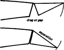
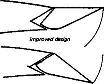
The lift and drag both act at the aerodynamic centre; the lift force does not in fact migrate to and fro. At the a. c. there will also be a pitching moment. In the case of symmetrical wings this is zero unless the flow separates, in which case it changes sharply to a nose down or negative force. With cambered wings of the usual kind there will always be a negative, nose down pitching moment, its strength depending almost entirely on the camber. The more nearly symmetrical the wing section is, the weaker the negative pitching moment As before, if the flow separates, the pitching moment changes as for symmetrical sections, becoming more negative.
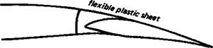
Some specially designed wing profiles, particularly those with reflexed camber, may have zero pitching moment like symmetrical sections, or, if the reflexing is exaggerated, a positive, nose up pitching moment may be made to appear. In fact an orthodox cambered profile, when inverted, behaves like a strongly reflexed aerofoil and tends to pitch nose up. (An example of a reflexed camber line is given in Figure 7.2).
When the airflow over the wing separates locally, as nearly always happens on model wings at low Reynolds numbers, the aerodynamic centre may sometimes move slightly from its expected location. Wind tunnel work in this area is still needed to be sure, but it seems that the lift point of action may vary either way perhaps by one or two percent, to 24 or 26%. For practical purposes, however, until research proves the contrary, modellers may take it that the 25% mean chord point is the place where the lift force acts. The mean chord is mentioned here because allowance must be made for any wing sweep, back or forward, when working out where the aerodynamic centre of the wing as a whole lies, as distinct from the a. c. of the aerofoil in the wing tunnel (See Figure 6.5 and Appendix 1)