Wake Capture
As discussed by Dickinson et al. [201] the wing-wake interaction can significantly contribute to lift production in hovering insects. They found that the second peak is generated at the beginning of each stroke of hovering flight when the wings reverse the direction of moving while rotating about the spanwise direction. This physical mechanism, termed wake capture, produces aerodynamic lift by transferring fluid momentum to the wing at the beginning of each half-stroke. A wing meets the wake created during the previous stroke after reversing its direction, thus increasing the effective flow speed surrounding the airfoil, which generates the second force peak. The wake-capture mechanism is illustrated in Figure 3.14.
As with rapid pitch-up, the effectiveness of wake capture is a function of wing kinematics and flow structure. This second force peak (occurring right after stroke reversal) is apparently distinct from rotational lift because its timing is independent of the phase of wing rotation. Dickinson et al. [201] showed that the second peak persists even by halting the wing after it rotates, indicating that the wake produced by the wing motion in the previous half-stroke serves as an energy source for lift production.
The sinusoidal motion along a horizontal stroke plane is similar to that shown by Wang et al. [217], who conducted 2D simulation of a hovering elliptic airfoil with the stroke amplitude ha between 1.4c and 2.4c, leading to a reduced frequency (Eq. (3-11)) k between 0.36 and 0.21. The Reynolds number considered is between 75 and 115. The computational results of Wang et al. [217] and Tang et al. [244] both identify a lift peak after the stroke reversal for the normal hovering mode (see Fig. 3.7). However, for the “water treading” mode, the results of Tang et al. [244] show a continuous increase in lift as the airfoil pitch angle increases to its maximum value without a noticeable peak. More detailed discussion of the lift generation for both normal and water treading hovering modes can be found in Tang et al. [244].
|
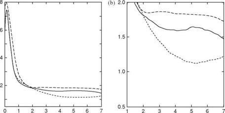
T T Figure 3.15. Drag coefficients of AR 6 and 2 flat plates during a starting-up translation as a function of T (the number of chord lengths the plate has traveled, see definition of [302]), from Ringuette et al. [299]. (a) Overall view; (b) detailed view of (a). Both (a) and (b) show drag coefficients for the free tip AR of 6 plate (continuous line) and for the same plate with the tip grazing a raised bottom (dash-dotted line); the dashed line is drag coefficient for the AR of 2 plate with the tip free. Low AR of the wing reduces the drag coefficient significantly due to interactions between a TiV and a LEV. |
This interpretation of wake-capture force generation has been questioned recently based on the claim that the rotation-independent lift peak is due to a reaction caused by accelerating the added mass of fluid [293]. In general, the inertia of the flapping wing is increased by the mass of the accelerated fluid – termed added mass [45] – which can play a significant role in the aerodynamics of insect flight [294]. However, evaluating the added mass, and thus estimating inertial forces, is, not easy. Although the mass of a wing itself may be tiny, the mass of the accelerated fluid need not be [65] [295].


