Longitudinal partial trim
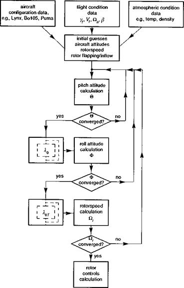
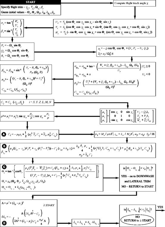
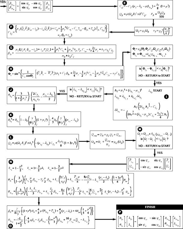
The main rotor thrust coefficient, longitudinal flapping and fuselage pitch attitude are calculated from the three longitudinal equations (A, B and C in Fig. 4.5). At this point, a comparison with the previous estimated value of pitch attitude is made; if the new estimate is close to the previous one, defined by the tolerance ve, then the partial longitudinal trim is held and the process moves on to the lateral/directional trim. If the iteration has not converged to within the tolerance, the process returns to the start and repeats until convergence is satisfied. Note that the new estimate of pitch attitude in Fig. 4.5 is given by
![]()
![]() ®ei – ®ei+ kei (gi-i – ®ei_i)
®ei – ®ei+ kei (gi-i – ®ei_i)
where
®e — ge (®e> Фє7 Vfe 7 Yfei ^aej ee7 Qr)
In some cases the iteration can diverge away from, rather than converge towards, the true solution, and the value of the ‘damping factor’ ke can be selected to ensure convergence; the smaller (< 1) the k factor, the slower, but more stable, is the iterative process. The key calculations in this longitudinal phase of the trim algorithm are the thrust coefficient, the longitudinal disc flapping and the pitch angle itself. For straight flight, the thrust remains relatively constant; in turning manoeuvres, the inertial term in the normal acceleration az, predominantly the Ue Qe term, will result in an increased thrust. The longitudinal flapping is derived from a more complicated expression, but essentially the rotor needs to flap to balance the resultant of the aerodynamic moments from the fuselage and empennage in straight flight. If the tail rotor is canted then an additional flap component will be required. Many helicopters are designed with a
|
Fig. 4.4 Sequence of calculations in the trim iteration – summary |
forward main rotor shaft tilt so that, at the cruise condition, the fuselage is level and the one-per-rev longitudinal flapping is zero or very small. We have already noted that the pitch angle is essentially derived from the ratio of drag to thrust, hence exhibiting a quadratic form with forward speed.
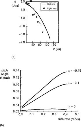
Figure 4.6(a) illustrates the variation of pitch angle with speed for HelisimBo105 together with a comparison against the DLR flight measurements. Note the hover pitch attitude of about 3°, due to the forward shaft tilt. The transition region is typically characterized by an increase in pitch angle as the main rotor downwash impinges on
|
Fig. 4.5 Part I – Sequence of calculations in the trim iteration – expanded form |
|
Fig. 4.5 Part II |
|
Fig. 4.6 Pitch angle in trim: (a) Trim pitch angle as a function of forward speed – comparison of flight and theory; (b) Trim pitch angle as a function of turn rate |
the horizontal stabilizer; this effect is evident in the flight, but not well predicted by simulation. Some helicopters feature a movable horizontal stabilizer to reduce this pitch-up tendency at low speed and to maintain a level fuselage in high-speed flight. In forward flight, the comparison between flight and theory suggests a higher full-scale value of fuselage drag than that used in the simulation; this is typical of the comparison with this level of modelling, with the simulation underpredicting the fuselage nose – down pitch at high speed by as much as 2°. In non-straight flight, the trim pitch angle will vary with turn rate and flight path angle. The strongest variations occur in climbing and descending flight, and Fig. 4.6(b) illustrates the kind of effect found on Lynx in climbs. The turn rate extends out to 0.4 rad/s, corresponding to a bank angle of nearly 60° at the 80-knot condition shown. As the climb rate increases, indicated by the increasingly negative flight path angle, the pitch angle to trim rises markedly; a negative flight path angle of -0.15 rad corresponds to a climb rate of about 1200 ft/min at the 80 knots trim speed. The increased pitch attitude at this steep bank angle is required to maintain zero sideslip. If the nose were set on the horizon in this condition
|
|
then the sideslip angle would correspond to the pitch angle shown in Fig. 4.6(b); the correct pitch attitude is achieved by balancing the turn with pedals, rather than pulling back on the cyclic stick.
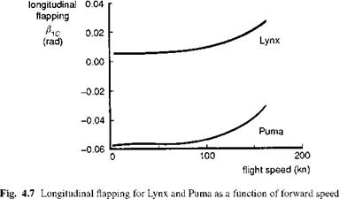
One further point on longitudinal trim relates to the differences between helicopters with different rotor types. Since the pitch angle is determined primarily by the ratio of drag to lift on the whole vehicle, we should not expect to find any significant differences in pitch attitude to trim between hingeless and articulated rotor helicopters, but we might expect to see differences in longitudinal flapping angle. Note the previous observation that the longitudinal flapping will compensate for any residual moment on the other helicopter components. Figure 4.7 compares the longitudinal disc tilt for the Lynx and Puma across the speed range. The large difference in trim flap at hover is partly due to the different baseline centre of gravity (cg) locations for the two aircraft. The Puma cg lies practically under the hub at the fuselage reference point; the hover flap-back then almost equates to the forward shaft tilt. For the Lynx, with its aft cg lying practically on the shaft axis, the hover flap is close to zero. For both aircraft, as forward speed increases, the disc tilts further forward, implying that the residual pitch moment from both aircraft is nose up (i. e., from the horizontal stabilizer). The change in disc tilt for both aircraft is only about 1.5° across the speed range.


