
Our heavyweight helicopter equal in the world does not have
In Rostov started production of the most load-lifting rotary-wing car The Russian holding «Helicopt[...]

Everything about aircrafts and helicopters. News and events in aviation worldwide. Civil, transportation, military helicopters and airplanes.

Everything about aircrafts and helicopters. News and events in aviation worldwide. Civil, transportation, military helicopters and airplanes.

Everything about aircrafts and helicopters. News and events in aviation worldwide. Civil, transportation, military helicopters and airplanes.

Everything about aircrafts and helicopters. News and events in aviation worldwide. Civil, transportation, military helicopters and airplanes.


5.1.2 Factors Involved
An exposition of blade element theory follows the same broad lines as used for hover (Chapter 3), taking into account, however, the extra complexities involved in forward flight. We begin by introducing the additional factors which enter into a forward flight condition.
Figure 5.15 shows a side view of the rotor disc – strictly a shallow cone as we have already seen. Motion is to the left and is assumed horizontal; that is to say, without a climb component. The plane enclosing the edge of the disc – the tip-path plane (TPP) – makes an angle ar with the oncoming stream direction. ar is reckoned positively downwards since that is the natural direction of tilt needed to obtain a forward component of the thrust necessary to maintain forward flight. We shall use small-angle approximations as required. The flight velocity V has components Vcos ar and V sin ar along and normal to the TPP. The advance ratio is given by:
![]() V cos ar V
V cos ar V
OR ‘ OR
as used previously. The total inflow through the rotor is the sum of V sin ar and Vi, the thrust- related induced velocity.
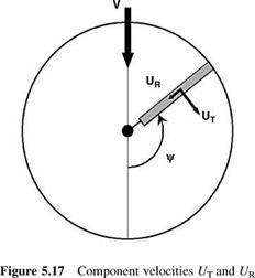
Referring to Figure 5.16, the resultant velocity U at a blade section is now a function of rotor rotation (i. e. rotor azimuth), helicopter forward speed, induced velocity and blade flapping motion. Components of U in the plane of the rotor rotation are UTand UP; additionally, because of the forward speed factor there is a spanwise component UR, shown in Figure 5.17. Components UT and UR are readily defined; to first order these are:
UT = Or + V sin C (5.35)
Ur = V cos C (5.36)
or, in non-dimensional form:
![]()
 |
uT = x + m sin c uR = m cos c
 |
|
The component UP has three terms, non-dimensionally, as follows: 1. The inflow factor:
2. A component of uR normal to the blade, which for a flapping angle b relative to the reference plane is seen (Figure 5.18) to be fiuR or:
b • m cos C (5.40)
3.
 |
A component resulting from the angular motion about the flapping hinge; at station r along the span, this is:
db_ db dC
![]()
 |
dt dC dt
– r• O. db
— r O dC
 |
|||
when non-dimensionalising with respect to tip speed this becomes:
Thus, combining these terms together,
![]() Up — l A bm cos C A x •
Up — l A bm cos C A x •
For small angles the resultant velocity U may be approximated by UT. The blade angle of incidence may be written as:
a — в—ф — в – — — в – — (5.44)
Ut Ut
Note that whereas the values of в and ф depend upon the choice of reference plane, the actual blade incidence a does not, so the expression (в — uP/uT) is independent of the reference plane used.


