Fluid Physics in O(102 to 103) Reynolds Number Regime
3.4.1 Effects of Kinematics on Hovering Airfoil Performance
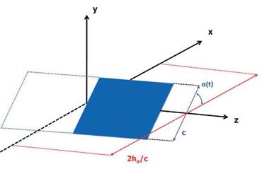
Trizila et al. [301] used surrogate modeling techniques [314] to investigate the time – averaged lift and power input subject to various combinations of kinematic parameters and reported numerous interesting findings. They considered a 2 percent thick wing with AR = 4. The Reynolds number, based on the average tip velocity, is equal to 64, which is similar to that of a fruit fly, Drosophila melanogaster. They used simplified wing kinematics (see Eqs. (3-4) and (3-5)) and selected the mid-chord of the rigid airfoil as the pitching axis. Because the free-stream is absent, the tip velocity is taken as the reference velocity, so that the reduced frequency contains the same information as the inversed normalized stroke amplitude [315]. The rotational (pitching) motion is similarly governed by the flapping frequency, and the angular amplitude, aa, is a measure of how far the airfoil deviates from the yz-plane (see Fig. 3.20). The time average of the pitching motion is a0 = 90°. Higher angular amplitudes yield lower angles of attack and vice versa. The phase lag between the pitching and plunging motions is denoted as q>.
The three kinematic parameters used as the design variables in surrogate modeling – stroke amplitude (ha), pitching angular amplitude (aa), and phase lag (<p>) – are varied independently. The range of the design variables is as follows. The normalized stroke amplitude is representative of a range of flapping wing flyers: 2.0 < 2ha/cm < 4.0. Details on pitch amplitude and phase lag are not as plentiful in the literature, so cases are chosen with low AoAs (amin = 10°; high pitching amplitude) and high AoAs (amin = 45°; low pitching amplitude): 45° < aa < 80°. The bounds on phase lag are chosen to be symmetric about the synchronized hovering: 60° < < 120°. Although delayed rotation is not a focus of many studies found in the
![]()
|
|
|
|
|
|
|||
 |
|||
|
|||
|
|||
|
|
||
|
|
||
|
|||
|
|||
|
|||
|
|||
|
|||
|
|||
![]()
(c) (d)
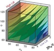
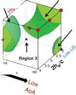
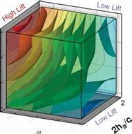
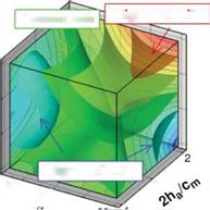
Figure 3.21. Iso-sufaces of 2D lift (a), 3D lift (b), 3D minus 2D lift (c), and (d) where the absolute difference between the 2D and 3D lift equals 0.10. The symbols denote training points in those regions for which detailed force histories and flow field quantities are available; brown octahedra (region 1), circles (region 2), black quarter sphere (region 3), and a blue cube (region 4). The blue region in (c) denotes kinematics for which the 2D lift is higher than the equivalent 3D kinematics. Likewise the yellow/red region denotes higher 3D time-averaged lift.
literature because of the lift-lowering rotational effects, the delayed rotation cases offer interesting wake interactions in 3D.
The quantities of interest – the objective functions in the surrogate modeling nomenclature – are the time-averaged lift coefficient and an approximation of the power required over the stroke cycle. Furthermore, based on the guidance from the surrogate models, Trizila et al. [301] probed the fluid physics associated with 2D and 3D cases and were able to highlight the effects of wing kinematics on hovering airfoil performance. The impact on lift from the 2D/3D unsteady mechanisms including interactions between the LEV and TiVs is detailed in subsequent sections.
Figure 3.21 shows the iso-surfaces of the time-averaged lift coefficient where each axis corresponds to one of the kinematic parameters (i. e., ha, aa, or <p). Figure 3.21a-c
correspond to the 2D lift, 3D lift, and the difference between the two, respectively. Observations that are immediately apparent are that kinematic combinations with a low aa (high AoA) and advanced rotation (high ф) have the highest mean lift in 2D and 3D. This result qualitatively agrees with the results of Wang et al. [217] and Sane and Dickinson [292]. Due to the non-monotonic response in phase lag (ф) found in the 2D lift response at high pitching amplitudes (see Fig. 3.21a), there are two regions where there is low, and possibly negative, time-averaged lift generation. The first region is defined by low plunge amplitudes (low 2ha/cm), low AoA (high aa), and advanced rotation (high ф). The second region is defined by low AoA (high aa), and delayed rotation (low ф) and is where the 3D kinematics also generates low time-averaged lift values.
A variable’s sensitivity is directly related to the gradients along the respective design variables, whereas a more quantitative measure is the global sensitivity analysis; these measures were examined in Trizila et al. [301]. The gradients along the aa and ф axes are much more significant than that along the normalized stroke amplitude. (Note: Lua et al. [316] found that the effect of Re is noticeably smaller than that of aa on the mean lift.) Furthermore, Figure 3.21 shows that advancing the phase lag is beneficial in 2D except when at high aa; in 3D there is no such exception within the bounds studied. Comparisons with Sane and Dickinson’s experiments [292] show qualitative agreement in the trends in time-averaged lift as a function of aa and ф within the common ranges, with the noticeable difference in setups being one study [301] used pure translation to represent the plunge whereas the experimental study flapped about a pivot point.
The difference between 2D and 3D time-averaged lift may raise a question about areas of the design space for which simplified 2D aerodynamic analyses can sufficiently approximate their analogous 3D counterparts versus those areas where there are substantial 3D effects, which would preclude such a comparison. Figure 3.21c suggests that the difference in the time-averaged lift coefficient larger than 0.1 is due to three-dimensionality.
Following Shyy et al. [296] and Trizila et al. [301], we now highlight four cases corresponding to those presented in Figure 3.21: (i) synchronized hovering, high AoA; (ii) advanced rotation, low AoA; (iii) delayed rotation, high AoA, low plunging amplitude; and (iv) delayed rotation, low AoA, and low plunging amplitude. Each of these cases represent a region where the lift for the low AR wing is significantly different in 2D than in 3D, as indicated in Figure 3.21. In addition to these cases, we look at another region where 2D lift is similar to 3D lift and discuss the trade-off between lift and power.


