Our heavyweight helicopter equal in the world does not have
In Rostov started production of the most load-lifting rotary-wing car The Russian holding «Helicopt[...]

Everything about aircrafts and helicopters. News and events in aviation worldwide. Civil, transportation, military helicopters and airplanes.

Everything about aircrafts and helicopters. News and events in aviation worldwide. Civil, transportation, military helicopters and airplanes.

Everything about aircrafts and helicopters. News and events in aviation worldwide. Civil, transportation, military helicopters and airplanes.

Everything about aircrafts and helicopters. News and events in aviation worldwide. Civil, transportation, military helicopters and airplanes.


The elementary torque is:
![]()
dQ — dH ■ r
— r(dDcosf + dLsinf)
Again there is a profile drag term, dQ0 say, and an induced term dQi. The former is readily manipulated thus (in coefficient form):
o
— 4s ■ Cdo ■ (1+m2)
The induced term, after a lengthier manipulation, is shown (Bramwell, p. 151) to be:
CQi — ICT-rnCHi (5.63)
giving for the total torque:
![]()
|
Using Equation 5.60 this becomes:
Cq = 4 s • Cd0 • (1Am2) aICt—m^Ha2 s • Cdo • m2
4 2 (5-65)
= 4 s • Cdo • (1+3m^ a1Ct—mCH
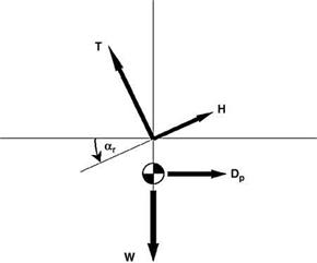
Now by Equation 5.39 the inflow factor l is a function of the inclination ar of the TPP, which clearly depends upon the drag not only of the rotor but of the helicopter as a whole. Examining the relationships for trimmed level flight, illustrated in Figure 5.20, we have approximately:
![]() (5.66)
(5.66)
![]() Tar — H A Dp
Tar — H A Dp
Dp being the parasite drag of the fuselage, including tail rotor, tailplane and any other attachments.
Thus:
|
|
|
|
|
li A mar
![]()
![]() ^ Dp A m
^ Dp A m
W
Using this in Equation 5.65, the power coefficient is expressed in the form:
cp = cq = ^iCT + 4s • Cd^1 + 3m2) + m (5.70)
which is seen to be the sum of terms representing the induced or lift-dependent drag, the rotor profile drag and the fuselage parasite drag. The first of these had already been derived (Equation 5.22) when considering the adaptation of momentum theory to forward flight.
In practice both the induced and profile drag power requirements are somewhat higher than are shown in Equation 5.70. An empirical correction factor k for the induced power was suggested in Equation 5.23. For the profile drag power the deficiency of the analytical formula arises from neglect of:
• a spanwise component of drag (Figure 5.19);
• a yawed-wing effect on the profile drag coefficient at azimuth angles significantly away from 90° and 270°;
• the reverse flow region on the retreating side.
The first of these factors is probably the most important. They are conventionally allowed for by replacing the factor 3 in Equation 5.70 by an empirical, larger factor, k say. Studies by Bennett [7] and Stepniewski [8] suggest that an appropriate value is between 4.5 and 4.7. Industrial practice tends to be based on a firm’s own experience: thus a value commonly used by Westland Helicopters is 4.65.
With the empirical corrections embodied, the power equation takes the form:
Cp = kiliCt +ts • Cd0 (1 + km2) + m — Ct (5.71)
4 W
This will be followed up in the chapter on helicopter performance (Chapter 7). In the present chapter we take our analytical study of the rotor aerodynamics two stages further: firstly examining the nature of the flapping coefficients a0, aj and b in terms of У, l and m; and secondly looking at some typical values of collective pitch У, inflow factor l and the flapping coefficients in relation to the forward speed parameter m and the level of thrust coefficient CT.