Extrapolation and Interpolation
11.1 Extrapolation and Numerical Instability
Extrapolation and interpolation are often used in large-scale computation. Here, extrapolation and interpolation on a regular mesh will be considered first. Interpolation on an irregular mesh will be discussed in Chapter 13. Most textbooks treat interpolation in great depth, but few discuss extrapolation. Some books state “extrapolation should only be used with great caution.” The warning is proper and real. It is a well-known fact in scientific computing that extrapolation often leads to numerical instability.
The most popular method for interpolation and extrapolation is the method of Lagrange polynomials. Suppose an N-point computation stencil with a mesh spacing Ax is used to extrapolate the values of a function f(x) to the point x0 + n Ax (n < 1) (see Figure 11.1). Without the loss of generality, x0 will be taken as the first stencil point. The Lagrange polynomials formed by the N mesh points are
(N. N—1 (x – x,)
lk)(x) = , k = 0,1, 2,(N – 1) (11.1)
j=0 (xk – xj) j=k
It is easy to verify that
![]() j = 0,1, 2,…, (N – 1)
j = 0,1, 2,…, (N – 1)
j = k
The extrapolated value of f at n Ax, according to the Lagrange polynomials method, is given by
N-1
f(x0 + nAx) f (xj)lf ) x + nAx), (11.2)
j=0
where f(x), j = 0,1,…, (N – 1), are the given values of f at the mesh points.
Despite the popularity of the Lagrange polynomials method, there is no known way to assess the errors quantitatively. Standard estimates given in textbooks are obtained by expanding the left and right sides of Eq. (11.2) by the Taylor series for
small Ax. This way yields an error of the order of 9N f/dxN |x (Ax)N if N mesh points are used for extrapolation. This error estimate is, however, not at all useful.
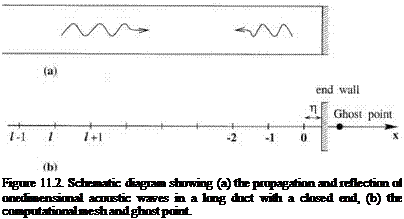
To provide an example of numerical instability arising from the use of the Lagrange polynomials extrapolation and to show that such an instability can be avoided by using an improved method, the problem of acoustic wave propagation and reflection in a long one-dimensional tube with a closed end will now be considered. The problem is shown schematically in Figure 11.2. Dimensionless variables with Ax as the length scale, a0 (sound speed) as the velocity scale, Ax/a0 as the time scale, p0 (ambient gas density) as the density scale, p0a2 as the pressure scale will be used. It will be assumed that the end wall of the tube is not at a mesh point, but at a distance n (n < 1) from the last mesh point at I = 0. The governing equations are the linearized momentum and energy equations.
![]()

d u d p
+ = 0 dt dx
d p d u
+ = 0. dt dx
The wall boundary condition is
u = 0 at x = n.

Suppose the problem is solved on a mesh as shown in Figure 11.2. To reduce dispersion error, the standard 7-point stencil central difference scheme (sixth order)
is selected to approximate the x derivatives. The semidiscretized forms of Eqs. (11.3) and (11.4) are
d + £ ajPi+j = 0 (11.6)
j=-3
d-d – + £ ajUe+j = 0. (11.7)
j=-3
Near the wall where a 7-point central difference scheme cannot fit, backward difference stencils are to be used. Since the wall is not at a mesh point, the value of и at the wall may be obtained by extrapolation using the values of и at the nearest 7 mesh points. Suppose Lagrange polynomials extrapolation is used. The wall boundary condition (11.5) becomes
6
J2u-kl(k} = 0. (11.8)
k=0
The ghost point method will be used to enforce this boundary condition. For this purpose, a ghost value of pressure is introduced at the ghost point I = 1. The ghost value is chosen so that Eq. (11.8) is satisfied at every time level of the computation.
Tam and Kurbatskii (2000) have solved this discretized problem analytically. Their solution reveals that for n > 0.42, this discrete system is numerically unstable. The system supports one boundary instability mode with time dependence e—imt where ю = mr + imi is the complex angular frequency. If юі is positive, the mode is an unstable mode. This instability can also be determined computationally by solving Eqs. (11.6) to (11.8) using a time marching scheme such as the fourth-order Runge – Kutta scheme. Figure 11.3 shows the computed value of рг at I = -3 as a function of time. By measuring the oscillation period and amplitude, the angular frequency юг and growth rate юі can be found. As shown in Figure 11.4, the numerically determined values of юг and юі are in good agreement with the analytical results.
The observed numerical instability of the acoustic wave reflection problem is due entirely to the use of Lagrange polynomials extrapolation formula. It will be shown later that, by using an improved extrapolation scheme, there is no numerical instability.


