
Our heavyweight helicopter equal in the world does not have
In Rostov started production of the most load-lifting rotary-wing car The Russian holding «Helicopt[...]

Everything about aircrafts and helicopters. News and events in aviation worldwide. Civil, transportation, military helicopters and airplanes.

Everything about aircrafts and helicopters. News and events in aviation worldwide. Civil, transportation, military helicopters and airplanes.

Everything about aircrafts and helicopters. News and events in aviation worldwide. Civil, transportation, military helicopters and airplanes.

Everything about aircrafts and helicopters. News and events in aviation worldwide. Civil, transportation, military helicopters and airplanes.


The flapping motion is determined by the condition that the net moment of forces acting on the blade about the flapping hinge is zero. Referring back to Figure 4.12, the forces on an element dr of blade span, of mass m dr, where m is the mass per unit span, are:
• the aerodynamic lift, expressed as an element of thrust dT, acting on a moment arm r;
• a centrifugal force rO2m dr, acting on a moment arm rb;
• an inertial force rfim dr, acting on a moment arm r;
• a blade weight moment, small in comparison with the rest and therefore to be neglected.
These lead to the flapping moment relationship given in Equation 4.3. Writing the aerodynamic or thrust moment for the time being as MT, we have:
•R fR
br2O2m dr + br2m dr = MT
|
|||
|
|||
|
|||
|
|||
|
|||
|
|||
|
|||
|
|
||
|
|||
|
|||
|
|||
|
|||
![]()
Now MT may be written:
|
||
|
||
|
||
|
||
![]()
so that, in dimensionless form:
|
|
|
|
|
|
|
|
![]()
where g is defined by:
|
|
|
|
|
|
and is known as the Lock number. It provides a ratio between the aerodynamic forces and the inertial forces which determine the centrifugal loads. Replacing uT and uP by their definitions in Equations 5.37 and 5.43, and substituting for b and db/dC, the right-hand side of Equation 5.78 develops to:
![]()
![]()
 1
1
2 g
where fS and fC represent functions in sin ф and cos ф respectively.
Since MT is independent of C, its value can be obtained by integrating only the first part of this expression. Hence:
|
|
||
|
|||
|
|||
|
|||
|
|||
|
|||
![]()
This is for an untwisted blade (У = constant У0) or in the usual way for a linearly twisted blade with У taken at three-quarters radius.
Also, because of the independence of MT the terms in sin C and those in cos C are each separately equatable to zero. These two equations yield expressions for the first harmonic coefficients aq and bq, namely:
|
|||
|
|
||
|
4
![]()
![]() 3 m^o 1 + 2 m"
3 m^o 1 + 2 m"
The three equations immediately above represent the classical definitions of flapping coefficients, in which У and 1 have been defined relative to the NFP. Equivalent, though rather more complex, definitions relative to the TPP are given by Johnson (p. 189) or Bramwell (p. 157). Bramwell’s equations, while not completely general, are probably accurate enough for most purposes and are quoted here for ease of reference (they are quoted in the order of calculation):
m
 |
|
|
|
||
![]()
The corresponding relationship for thrust coefficient is:
л . – zi ^t ma1
3 V1 + 2m j 2 2
|
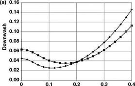
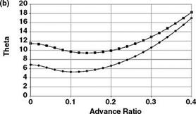
Advance Ratio |
|
Figure 5.21 (a) Calculated values of 1T v m. (b) Collective pitch в v m |
From the preceding discussion, two reference planes have been quoted, namely the TPP and the NFP. The previous analysis used the NFP; however, the rotor downwash is intimately linked with the rotor disc or the TPP. Bramwell’s equations (5.84)-(5.87) quote the l term in terms of the TPP. To avoid confusion, the subscript T is used for the downflow term (1T). This also links naturally with the definition of l in Equation 5.39. The 1T notation is also used in Figure 5.21.
 Без верификации!")