The derivatives Mw, Mv and Mv
Before leaving the pitching moment derivatives with speed, it should be noted that the incidence at the empennage is a combination of the fuselage incidence and the effect of the rotor downwash at the tail. This effect will normally be taken into account when perturbing the forces and moments with the w perturbation; the rotor thrust and the downwash will change, resulting in an incidence perturbation at the tail. The magnitude of the downwash at the tail depends on the distance between the tail and rotor. Let a f be the fuselage incidence, д the advance ratio and Xtp the downwash at the tail. We can write the incidence at the tail in the form
The downwash at the tail at time t was generated at the rotor disc at time t — ltp/Ue earlier. If we assume that this time increment is small compared with the response time, we can write
where ktp is the amplification factor on the downwash. The incidence at the tail therefore depends explicitly on the rate of change of rotor inflow with time. Applying the theory of small perturbations, we can write this downwash acceleration as a linear combination of the rates of change of aircraft states and controls, i. e.,
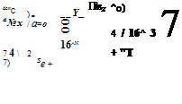
Thus, we find the appearance of acceleration derivatives like Mw in the longitudinal motion, for which analytic expressions are relatively straightforward to derive from the thrust coefficient and uniform inflow equations. The presence of non-uniform inflow and wake contraction complicates the overall effect, reducing the validity of the above simple approximation. Nevertheless, the physical mechanism is very similar to that found on fixed-wing aircraft where the downwash lag at the tail, attributed entirely to incidence changes on the main wing, leads to an effective acceleration derivative.
Any lateral variation in rotor downwash at the tail will also lead to changes in pitching moments during yaw manoeuvres. This effect is discussed in Refs 4.8, 4.9 and 4.10 where relatively simple flat wake models are shown to be effective in modelling the pitching moment due to sideslip (see Chapter 3), leading to the derivatives Mv and Mv, in a similar fashion to the effect from w perturbations.
 |
|
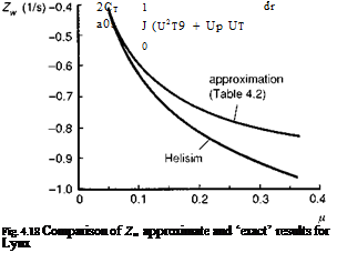
and in forward flight. The derivative Zw represents the initial acceleration following an abrupt vertical gust and is inversely proportional to blade loading (see Chapter 2, eqn 2.63). The much higher typical blade loadings on rotorcraft, compared with fixed-wing aircraft of similar weight, partly account for the smaller values of Zw, and hence lower gust sensitivity, for helicopters in forward flight. A second major factor is disguised in the variation of the heave damping with speed. The forward flight approximation in Table 4.2 is shown plotted against the Lynx value from the Helisim simulation model in Fig. 4.18; the 10% difference at the higher values of advance ratio is attributed to the fuselage and tail. The variation is seen to level off at higher speeds, while the gust sensitivity of fixed-wing aircraft continues to increase linearly with speed (see Fig. 2.28). As discussed in Chapter 2, the reason for the asymptotic behaviour of the helicopter damping stems from the increased harmonic distribution of the airloads as the speed increases. The thrust coefficient can be written as
and the in-plane and normal velocity components can be approximated by the expressions
U t ~ r + p sin ф, Up = nz — ki — cos ф — r в’ (4.70)
The harmonic components of thrust in the expanded form of eqn 4.69 therefore define the level of quasi-steady and vibratory loads that reach the fuselage. Perturbations in w show up in the second term in parenthesis in eqn 4.69. The component that increases linearly with forward speed is also a one-per-rev loading. Hence, while the zero-per – rev or quasi-steady term levels off at higher speeds, the vibratory response to a gust at. Nb-per-rev, where Nb is the number of blades, continues to increase. While these loads do not result in significant flight path or attitude changes, and therefore are unlikely to cause handling problems, they do affect the overall ride quality. Further discussion on the general topic of ride quality is contained in Chapter 5.
The derivatives Lv, Nv
 |
||||
The remaining velocity derivatives belong to the lateral/directional DoFs and the most significant are the sideslip derivatives – the dihedral effect Lv and the weathercock stability Nv. The magnitude of these two moments as sideslip increases determines the lateral/directional static stability characteristics. A positive value of Nv is stabilizing, while a negative value of Lv is stabilizing. Both have the same kind of effects on rotarywing as on fixed-wing aircraft but with rotary-wing aircraft the new component is the tail rotor which can contribute strongly to both. The magnitude of the tail rotor contribution to the dihedral effect depends on the height of the tail rotor above the aircraft centre of mass. The fuselage can also contribute to Lv if the aerodynamic centre is offset vertically from the centre of mass, as in the case of deep fuselage hulls, which typically leads to a negative Lv component. But once again, the main rotor is usually the dominant effect, especially for helicopters with hingeless rotors, where all the main rotor moments are magnified roughly proportionally with the rotor stiffness. In hover, the derivative Lv is generated by similar aerodynamics to those of the pitch derivative Mu, and as forward flight increases some of the basic similarities remain. As the blades are exposed to the velocity perturbation, the advancing blade experiences an increase in lift, the retreating blade a decrease, and the one-per-rev flapping response occurs approximately 90° around the azimuth, giving a rolling moment to port (starboard for clockwise rotors) for a lateral velocity perturbation and a pitch-up moment in response to a longitudinal velocity perturbation. The extent of the flap response depends on the rotor stiffness, the Lock number and also the trim lift on the rotor blades. To examine the flap derivatives we can refer back to eqns 3.70, 3.71 and 3.72 from Chapter 3. At hover, we can write
or, for the special case of a rotor hinged at the hub centre, the flap response depends only on the trim lift on the rotor blades, i. e.,
The dihedral effect can therefore potentially change sign for teetering rotors at low and negative rotor thrust conditions that are outside the operational flight envelope for such aircraft, because of such reversals of flap response and the associated hub moments.
The directional stability derivative Nv is critically important for both static and dynamic stability of helicopters. The main contributors are the tail rotor, the vertical fin and the fuselage. The latter is usually destabilizing with the fuselage centre of pressure behind the centre of mass; both the tail rotor and vertical fin are stabilizing (i. e., positive). All are approximately linear with speed up to moderate forward speeds. However, the contribution from the tail rotor is similar to the heave damping on the main rotor, arising from a change in tail rotor thrust due to a change in velocity normal to the disc, and levels off at high speed; the contributions from the fin and fuselage continue to increase in the positive and negative senses respectively. The weathercock
|
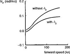
Fig. 4.19 Effect of tail rotor S3 angle on weathercock stability derivative Nv |
stability is strongly influenced by the tail rotor S3 angle (see Chapter 3, Section 3.2.2) which reduces blade pitch as a function of blade flapping. On the four-bladed Lynx tail rotor, changes in tail rotor thrust lead to changes in rotor coning and hence changes in tail rotor collective. Figure 4.19 illustrates the comparison of Nv for the Lynx, with and without S3, showing that S3 produces a reduction of about 40% at high speed.
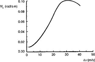
For the Lynx, the low-speed values of Nv tend to be dominated by the inertia coupling with roll (and hence the much stronger dihedral effect Lv) through the product of inertia Ixz (see eqn 4.48). The reduced effectiveness of the tail rotor to directional stability makes the contribution of the vertical fin all the more important. For helicopters with high set tail rotors, these vertical surfaces also carry the tail rotor drive shaft and can have high ratios of thickness to chord. Aerofoil sections having this property can exhibit a flattening or even reversal of the lift curve slope at small incidence values (Ref. 4.11). In such cases it can be expected that the yawing moment due to sideslip will exhibit a strong nonlinearity with sideslip velocity. The Puma features this characteristic and the associated effects on stability have been discussed in Ref. 4.12; the fin aerodynamics are summarized in the Appendix, Section 4B.1. Figure 4.20 shows how the value of
|
|
Nv for the Puma varies with the magnitude of the velocity perturbation at a trim speed of 120 knots. At small amplitude, up to about 5 m/s perturbation (corresponding to about 5° of sideslip), the fin contributes nothing to the weathercock stability. As the perturbation is increased up to 30 m/s (corresponding to nearly 30° of sideslip) there is a tenfold increase in Nv. The effects of this nonlinearity on stability and response will be discussed later, but are obviously significant and need to be taken into account in the linearization process.


