Fluid Physics in O(104 to 105) Reynolds Number Regime
Natural flyers such as insects and birds have wings thinner than those of conventional airplanes, such as NACA 0012 or SD7003 airfoils. The effects of kinematics at Re of O(102) in terms of St and к on aerodynamics were discussed in Section 3.4. In this section the effects of airfoil shape on the performance of flapping airfoils at Re of O(104) play a central role in discussing the effects of kinematics, Reynolds number, and 3D as well.
Lentink and Gerritsma [319] investigated numerically the effects of airfoil shape on aerodynamic performance in forward flight. Even though the Reynolds number considered in their study is O(102), they concluded that a plunging thin airfoil with aft camber outperformed other airfoils, including the more conventional airfoil shapes with thick and rounded leading edges. One exception was the plunging N0010 airfoil, which due to its largest frontal area had good performance. At a Reynolds number of 5.0 x 10³, Usherwood and Ellington [320] examined experimentally the effect of airfoil shape of a revolving wing with a planform representative of hawkmoth wings. The results showed that detailed leading-edge shape and airfoil twist and camber do not have a substantial influence on aerodynamic performance.
Sane [312] used Polhamus’s [321] leading-edge suction analogy to explain the lift characteristics of thinner airfoils. The flow around rounded leading-edge airfoils remains attached, creating a leading-edge suction force parallel to the airfoil chord, tilting the resulting aerodynamic force forward toward the incoming flow, and reducing drag. In contrast, flow over an airfoil with a sharp leading edge separates at the leading edge, forming an LEV. The suction force due to the LEV acts normal to the airfoil, increasing both lift and drag. More recently, Ashraf, Young, and Lai [322] numerically investigated the effects of airfoil thickness on combined pitching and plunging airfoils at к = 1 and Reynolds numbers varying from 2.0 x 10² to 2 x 10⁶. They found that at lower Reynolds numbers thin airfoils outperformed thick airfoil, whereas at higher Reynolds numbers the thick airfoil show better performance.
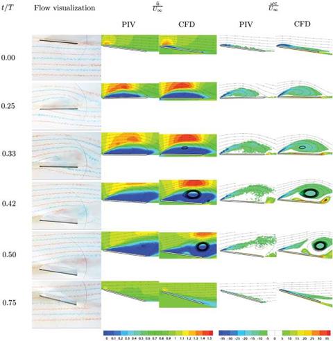
Initiated by the Research Technology Organization (RTO) of NATO, multiple institutions from several countries have investigated the unsteady flow around a pitching and plunging airfoil at Re = O(104) using different methodologies. Ol et al. [323] numerically and experimentally considered the interplay between a SD7003 airfoil undergoing either combined pitching and plunging or purely plunging motions and the resulting aerodynamics at Reynolds numbers 1 x 10⁴, 3 x 10⁴, and 6 x 10⁴ at a fixed Strouhal number and reduced frequency: St = 0.08 and к = 0.25. The two different kinematics produced a shallow stall (under combined pitching-plunging) and a deep stall (under purely plunging) of the instantaneous flow about the airfoil. Kang et al. [324] further reported results on the flow physics of a 2.3 percent thickness flat plate in 2D and 3D configurations and an SD7003 airfoil. In particular, they
|
Figure 3.33. Dye injection, и1/Ц0 and vorticity contours from the flow field around the 2D flat plate in shallow stall at Re = 6 x 10⁴ from Kang et al. [324]. |
showed that due to the small LE radius of curvature of the flat plate, the flow field is dominated by an LEV on the suction side, which could be utilized to manipulate lift production. Furthermore, Sane’s use of Polhamus’s analogy [321] was confirmed for the shallow stall motion.


