Our heavyweight helicopter equal in the world does not have
In Rostov started production of the most load-lifting rotary-wing car The Russian holding «Helicopt[...]

Everything about aircrafts and helicopters. News and events in aviation worldwide. Civil, transportation, military helicopters and airplanes.

Everything about aircrafts and helicopters. News and events in aviation worldwide. Civil, transportation, military helicopters and airplanes.

Everything about aircrafts and helicopters. News and events in aviation worldwide. Civil, transportation, military helicopters and airplanes.

Everything about aircrafts and helicopters. News and events in aviation worldwide. Civil, transportation, military helicopters and airplanes.


All these features of the NACA ‘6’ profiles were recognised in the 1950s by designers of full-sized sailplanes. The great width of the low drag range of the thicker profiles at sailplane Re led to the adoption of profiles such as the NACA 633618 and 633621 for such successful types as the Ka 6 and Skylark series respectively. The performance, particularly at high speeds, was a vast improvement on earlier types such as the Olympia and Weihe which had thinner wings (Gdttingen 549) but with turbulent flow. However, although the new profiles were cambered for ci 0.6, and worked efficiently up to ci 0.9 and
|
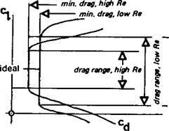
Fig. 9.7 The low drag range at high and low Re |
a little beyond (because of the wider low drag bucket at low Re), there were still problems at higher c|. Cambering the wings more led to flow separation at the low speed end of the range, and tended to spoil the high speed performance below сі 0.3. How the ‘6’ series profiles perform at Re lower than 700,000 is hardly known, since few wind tunnel tests have been carried out below this figure. They have been successfully used on man – powered aircraft and a few of the better hang gliders. They should perform very well on fast models, providing the correct camber value is chosen. The temptation to thin the profile on a speed model too much should be resisted. For practical racing, a thicker profile is less sensitive to errors and enables turns to be flown economically without danger of sudden increases of drag.
For scale model sailplanes, the great thickness of the typical ‘6’ series aerofoils used on the prototypes may cause difficulties. Such aerofoils still have a critical Re below which flow will separate and not re-attach. Unless the model is very large in chord, the profile, while it should retain a laminar flow thickness form, will require thinning down. Of course, full-size sailplanes have very narrow, high aspect ratio wings. The very thick aerofoils on such types as the Skylark 2,3 and 4 are not suitable for small models of these aircraft Their wide low drag range cannot, therefore, be employed on small models. The same applies to more recent sailplane designs which still may have aerofoils of 17% thickness, with even higher a. r. Earlier, pre-laminar flow sailplanes make more suitable prototypes for scale modelling since they usually had lower aspect ratios (broader chord), and thinner aerofoils. However, some of these aerofoils had unduly large leading edge radii and hence high critical Re. Scale model sailplanes should, in general, be as large as possible if the same aerofoil is to be used on the prototype. Otherwise the flying performance will be very disappointing. The same argument applies, of course, to all scale models, but with full-sized powered aircraft speed range is less important so the aerofoils used are usually as thin as possible for the sake of efficiency at one speed. Hence the scale aerofoil tends to have a lower critical Re and there is more prospect of success for the small model. Also, with most prototypes, there are irregularities in the neighbourhood of the leading edge which allow the modeller to ‘turbulate’ the airflow. This applies with special force to so-called ‘peanut’ scale models. Some of the best full-sized prototypes for such models are the very early aeroplanes which had thin wings resembling the curved plate profiles of the previous chapter.
|
|
In designing aerofoils the next important steps forward were taken by R. Eppler and F. X. Wortmann, working independently in Germany during the 1950s and 60s. Eppler’s early full-sized sailplane profiles should not be confused with those he has more recently produced for models. They are designed on different principles, and may be distinguished by their more complex-seeming designations, such as EA 8 (-1) 1206. (One such experimental section was, unlike the others, intended for models, and has been tested by Kraemer in the wind tunnel. The results are given in Appendix 2, the Gottingen number being 804.) On full-sized sailplanes, the earlier Eppler profiles are now rarely employed, although in their day they were a distinct improvement, as far as speed range was concerned, over the NACA ‘6’ profiles. Eppler argued that sailplanes never operated at one design value or ideal Cl, but were always either climbing in thermals at minimum sink corresponding to high cj, or ‘penetrating’ at low Cl (see Fig. 4.3). Rather than trying to widen the low drag range of NACA profiles, he designed profiles which in effect split the bucket into two, as indicated in Figure 9.8. The first glassfibre sailplane, the record breaking Phonix, had a profile of this type, and so did the subsequent Phoebus series. The original (wooden) Standard Austria design with the NACA 652415 profile was much improved when it was re-winged with an Eppler profile to create the SH 1, even though this profile was slightly thicker. Eppler achieved his results by designing for laminar flow on one surface of the wing at high angle of attack, and the other surface at low angles of attack. In between, both surfaces were turbulent, but he argued that this hardly mattered. Flight measurements on the Phonix confirmed his theoretical expectations. It is, however, doubtful if these profiles are of value in modelling, and they will not be discussed further here.
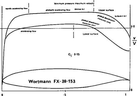
F. X. Wortmann’s work followed a different line.* On full-sized sailplanes, at the 1974 World Championships every sailplane competing had Wortmann aerofoils. The thinner examples work well on larger model sailplanes. Some of the less cambered Wortmann profiles might also be superior to the NACA ‘6’ series for racing powered models. Wind tunnel results are promising. For gliders Wortmann concentrated on widening the low drag bucket of laminar flow profiles, using electronic computer techniques to achieve the desired grading of the velocity distribution curves.
The velocity distributions of the NACA profiles, as shown in Figure 9.3, exhibit a sharp kink in the curve at the maximum velocity/minimum pressure point A straight line was drawn from here and the profile thickness designed to produce this sharp change. The airstream velocity after the sudden onset of deceleration slows down at a steady rate all the way. At low Re the separation bubble forms, on such a profile, almost immediately behind the minimum pressure point. After re-attachment, the turbulent boundary layer steadily loses momentum, and although it does not separate immediately, as it becomes slower and slower it loses its ability to maintain contact with the wing, and some separation is very likely before the trailing edge is reached. This separation marks the limit of the low drag bucket At lower Re, to take advantage of the natural tendency to greater laminar flow, the sharp kink in the curve, Wortmann argued, should be smoothed out. The laminar boundary layer would then be able to persist further behind the minimum pressure point, and if the flow deceleration over this portion of the wing was gradual, it might be capable of continuing even as far as 70% of the way to the trailing edge. Transition, with separation bubble, would eventually come, however, and here again a different principle was needed. After transition, the boundary layer has plenty of momentum (providing it has not completely separated), and can remain attached to the wing even against a sharp pressure gradient As it nears the trailing edge, the energy * Professor Wortmann died in 1985.
available is less, so it should be required to fight a less severe gradient. The result of this reasoning in terms of graded velocity profile for a man-powered aircraft aerofoil is shown in Figure 9.9 and for a high speed aerofoil in Fig. 9.10.
Profiles designed around these principles have been extensively tested in wind tunnels and in flight, and the expected results are achieved. The low drag bucket is no longer so flat-bottomed, i. e. there is some increase of cd as the ci rises above the designed value, but * the total width of the ‘bucket’ is considerably more than that of equivalent NACA profiles. Performance at high ci is better. Ordinates for the thinner types of Wortmann profile are given in Appendix 3. The thicker profiles are probably not good for models. The FX 63-13.7 has been tested extensively by a number of different research organisations over a considerable range of Re numbers. It is too strongly cambered for most model applications, since it was designed for a man-powered aircraft. A number of flapped sections is also given. The flapped profiles give good results only if the flap is of the correct size, as specified, and the flap should be set correctly for each flying speed. If this is not done, the profile is actually less efficient than the un-flapped versions. However, with flaps correctly used and gaps sealed, the width of the low drag range is even further increased.
The Wortmann aerofoils are mutually compatible with one another for use in tapered wings. In particular the FX 60-126 was intended for use at wing tips. It has a late stall and so may be employed without washout, or only a very small amount Large model sailplanes have been successful with these profiles. The FX 60-100, a thinner version, has been very popular with model fliers. At Re lower than 100 to 200 thousand the behaviour of most Wortmann sections remains to be investigated.
|
Fig. 9.10 Calculated velocity gradients over a Wortmann high speed aerofoil. 15.9% thick |
The aerofoils designed specifically for models by R. Eppler have achieved great popularity. They range from thin, highly cambered profiles intended for free-flight ; duration models, to much thicker sections for large sailplanes. By an extension of his < earlier thinking, Eppler designed these profiles so that a pressure gradient favourable for laminar flow is preserved as far as possible on at least one surface of the wing – the upper ■ surface at low angles of attack, die lower surface at high angles. However, at some intermediate angle, instead of both surfaces being turbulent (as with his full-sized profiles, Fig. 9.7), there is a range of angles over which laminar flow should exist on both surfaces for some distance. Examples, in terms of computed velocity distributions, are shown in Figures 9.11 – 9.13. At 9 degrees angle of attack the E 203 profile has an accelerating boundary layer on the underside up to about 35% of the chord. (The speed of flow remains less than that of the mainstream, to produce positive pressure.) After the maximum velocity point, the decrease is very gradual, so there is every chance for the laminar boundary layer to persist for some distance, and then become turbulent On the
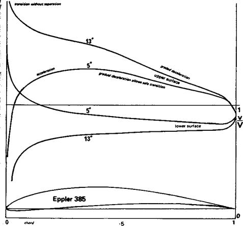
r This profile is designed for large models, and there should be no danger of premature stall. ‘ After the separation bubble the boundary layer re-attaches, overcomes the adverse I pressure gradient and remains attached – At zero angle of attack, close to the zero lift angle I for this profile, the upper surface has laminar flow while the underside now has the early I pressure peak and gradual deceleration thereafter. At angles between these two, the jj profile should have extensive laminar flow on both surfaces, and the minimum profile drag N will be achieved. This is a relatively high speed profile. A similar set of curves for a lower і speed profile, the E 385, is shown in Figure 9.12.
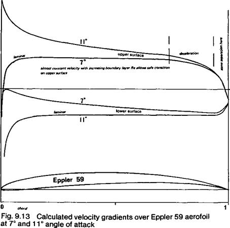
г For very low Re, the thin profiles E 58 and 59 have been designed. The likelihood of I flow separation at low Re is much greater, as stressed in Chapter 7, and Eppler admits I that some separation does occur even on these very thin profiles due to the very sharp [‘ decrease of flow speeds near the trailing edge on the upper surfaces (see Fig. 9.13).
? However, at the designed angle of attack, the computed velocity and pressure gradient on » the upper side is almost constant over a large proportion of the chord. This allows the jf laminar boundary layer to continue as far as possible and make a safe transition to
|
Fig. 9.12 Calculated velocity gradients over Eppler 385 aerofoil at 5° and 13° angle of attack |
|
|
turbulent flow either as or before the deceleration begins. Although, as with all thin, highly cambered profiles, such wings will be critical in trimming and will require large stabilisers, the performance gain should be worthwhile. This is, of course, still subject to the limitation that profile drag on a model at low speed is relatively much less significant than aspect ratio. Unlike the ‘turbulent flow’ aerofoils of the previous chapter, these profiles should be built without leading edge waviness. Sheet balsa covering or even solid balsa construction at least over the front half of the wing should be regarded as essential. Theoretical drag polars of several Eppler aerofoils are given in Figure 9.14 and 9.15.