Our heavyweight helicopter equal in the world does not have
In Rostov started production of the most load-lifting rotary-wing car The Russian holding «Helicopt[...]

Everything about aircrafts and helicopters. News and events in aviation worldwide. Civil, transportation, military helicopters and airplanes.

Everything about aircrafts and helicopters. News and events in aviation worldwide. Civil, transportation, military helicopters and airplanes.

Everything about aircrafts and helicopters. News and events in aviation worldwide. Civil, transportation, military helicopters and airplanes.

Everything about aircrafts and helicopters. News and events in aviation worldwide. Civil, transportation, military helicopters and airplanes.


This work is an approach to compute supersonic flowficld models which arc mathematically simulating a part of the inviscid flow past an aerodynamic configuration. For wavenders, these flows will be bounded by a shock wave, a stream surface defining a solid body contour, and an exit surface. Such boundanes allow to place this model within given supersonic upstream flow conditions, connected along the shock by the Rankine – Hugoniot relations
8.2.1 Crass – marching in supersonic flow
An earlier, similar approach, as described tn the previous book chapter, was aimed at connecting a local supersonic flow field with surrounding subsonic flow along a prescribed sonic line. This procedure was used to model transonic flows with applications in supercritical w ing design This process was first earned out as a linear method of characteristics, it is equivalent to marching in a direction normal to the flow (“cross – marching”), thus allowing for a start at initial conditions compatible with embedded supersonic flow domains.
Locally axisymmetric flow
Within 2D inviscid supersonic flow, a local linearization of the basic equation for a velocity potential Ф gives the wave equation
(68)
![]() where x is the direction of the local flow vector. We realize that both x and z are time-
where x is the direction of the local flow vector. We realize that both x and z are time-
 |
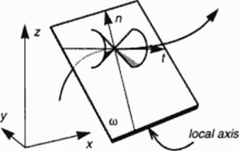
like directions, a marching in the flow direction or normal to it are mathematically equivalent, their choice determined only by formulation of the initial conditions, sec Figure 44.
Axisymraetric flows axe a special case of 3D flows, but their computation may also be earned out in a 2D meridional plane by the method of characteristics. It can be shown that the axisymmctric model equation for linear supersonic flow
![]() (69)
(69)
can be used to second order approximate locally a 3D flow element which is a solution to the general 3D flow equation
(70)
Location of the axis of this osculating axisymmetnc flow depends on local flow curvature and velocity gradient. This can be used to develop a 3D method of characteristics, which has locally 2D properties and therefore reduces perturbation amplification in a numerical cross * marching approach
Figure 45 illustrates 2D flow and the possibility to locally approximate 3D flow by an axisymmetnc flow model.
 |
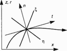 |
Figure 45 Two • and three-dimensional flow. Normal and tangential vectors n. t.
Osculating plane (i) to streamline as a meridional plane of osculating axisymmetric flow, characteristic lines x, h in 2D flow, Mach conoids in 3D flow.
The abovcmentioned idea of cross – inarching is intended to familiarize the reader with a strategy of numerically integratung flow model equations from initial data determined solely by unperturbed upstream flow and a geometrically defined oblique shock wave. The flow held behind this shock has to be evaluated by using the method of characteristics, for irrotational flow equivalent to a potential flow solver, for rotational flow resulting from an arbitrarily curved shock wave equivalent to an Euler solver. Boundaries given for and resulting from characteristics calculation in the following will be explained for the simple flow past a wedge, because using a marching code later will require to keep in mind regions of dependence if a numerical scheme should work properly.
The flow past a wedge is sketched in Figure 46 to show how cross – marching will be used to obtain the flow field solution in part or in whole. Let supersonic flow be deflected by a wedge contour AG. A shock AB forms end bends the streamlines within triangle AGB conformal to the wedge anglcWc ask now for the inverse computational approach to find the flow and the contour behind the given portion AB of the shock wave. Characteristics resulting from cross – marching will define a triangular region of dependence ABC. which includes a non-physical part of the solution beyond the contour AD. which results from flow field integration within ABC. On the other hand. a part DBG of the physical solution is not available with initial data given only along AB. Data need to be given also along a portion BE of the exit, with results along CB available this defines the solution within the polygon CBEF. Evaluation will define the streamline continuation beyond D toward an exit value at Gsituated on BE or EF. depending on the choice of E. For high supersonic Mach numbers, contour length AD may be only a fraction of the continuation DG.
 |
For curved shock waves prescribed, we have to expect rotational post-shock flow resulting from the computation. The contour streamline is another characteristic now. cross • marching requires avoiding contradictory initial data along AB and BE, if both domains have to be solved. Furthermore, data for entropy or vorticity distribution arc not defined beyond the contour (to be computed!, which may pose a problem for cross • marching.
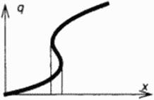 |
Another feature of cross – marching with the method of characteristics is the possibility of limit lines occurring in the computed flow. A multivalued solution may he found because the marching is essentially carried out in a hodograph plane: i. e. a variable of slate, for instance the velocity q. is the independent variable to march along, w hile coordinates x of physical space arc resulting, see Figure 47. Such a solution cannot be obtained by marching in physical space: the marching direction would have to be reversed to pick up a continuous solution q(x). Occurrence of a limit line or surface alerts us that the given shock wave is not compatible with a smooth flow downstream of it. the initial data should be changed.
![]() Representative variable of state q as a function of representative space coordinate x: multivalued solution if limit lines (surfaces) occur.
Representative variable of state q as a function of representative space coordinate x: multivalued solution if limit lines (surfaces) occur.
We draw some conclusions from this outline of models to be simulated numerically and used for practical design aerodynamics:
Caveats for a numerical cross ■ marching integration concept
1. Given oblique shock waves require cross – marching to obtain a contour compatible with initial conditions.
2. Cross – marching in 2D plane or axisymmetnc flow is effectively carried out by wrll – posed hodograph (inverse) methods of characteristics.
3. 3D flows may be approximated locally by (osculating) axisymmetnc flow.
4. Extent of contours designed with cross – marching may be small compared to extent of the given shock wave in high Mach number supersonic flow.
5. Rotational flow constrains region of dependence to physical flow bounded by designed contour.
6. Occurence of limit surfaces requires initial data modification; inverse marching allows to pick up limit lines, direct space marching results in infinite gradients.
|
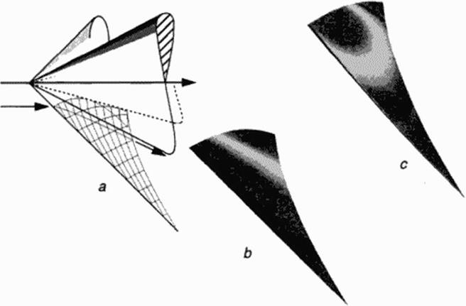
Figure 48 Mach number М» = 2. circular cone flow integration and flow element past a curved shock wave. Given shock cone angle 45* (a), resulting solid cone angle 27.32° and analytical continuation toward limit cone (18.5°) within solid cone boundary. Isomach fringes of conical (b) and curved shock (c) flow field. |