Our heavyweight helicopter equal in the world does not have
In Rostov started production of the most load-lifting rotary-wing car The Russian holding «Helicopt[...]

Everything about aircrafts and helicopters. News and events in aviation worldwide. Civil, transportation, military helicopters and airplanes.

Everything about aircrafts and helicopters. News and events in aviation worldwide. Civil, transportation, military helicopters and airplanes.

Everything about aircrafts and helicopters. News and events in aviation worldwide. Civil, transportation, military helicopters and airplanes.

Everything about aircrafts and helicopters. News and events in aviation worldwide. Civil, transportation, military helicopters and airplanes.


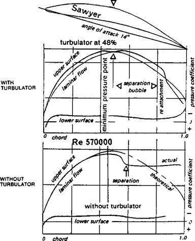
There is some evidence to suggest that even a ‘laminar’ flow wing may be improved by careful use of a ‘trip strip’ turbulator. It has been shown earlier that when a laminar boundary layer meets an adverse pressure gradient, separation may occur. If a laminar flow profile, such as one of those designed by Wortmann or Eppler, suffers from flow separation behind the minimum pressure point, by placing a turbulator strip just ahead of the danger point, the boundary layer may be forced into turbulence a little early. When it arrives at the critical spot it may have enough momentum in its lowest layers to carry it through. In Figure 9.21 the results of an experiment by Sawyer with a turbine cascade blade not unlike a model wing profile in appearance are given. Although these tests were carried out at a Re of 570,000, higher than that of all but the larger and faster models, they do indicate a possible, and encouraging, line for experiment. The angle of attack of these tests was very high — about 14 degrees. Some degree of flow separation might have been thought inevitable so close to the stall. Separation on the plain aerofoil did occur on the upper side shortly after the pressure minimum, which was at 50%. This is indicated on the diagram by the sharp rise of pressure and the flat segment of the curve trailing aft. The whole rear part of the wing profile was stalled. By placing a thin trip strip just ahead of the 50% position, a separation bubble was brought into being. The flow re-attached as a turbulent boundary layer at about 80% chord — i. e. the bubble extended over 30% of the wing. After re-attachment, the pressure returned almost to the desired theoretical value and the profile was very efficient. Compare this also with Pfenninger’s results on a very thin profile, given in Appendix 2, at Re’s down to 100,000. It seems likely, therefore, that models using laminar flow profiles may also be tried with trip strips near the minimum pressure point on the wing, which for practical purposes may be assumed to lie near the position of maximum thickness.
Misplacing of the turbulator can do more harm than good. Results of a test on the Eppler 65 are shown in Figure 9.20. With a turbulator at 28% of the chord on the upper surface
Separation bubble warning
_ _ _ _ _ _ д upper surfoce
 |
E 6b Trb. 28% .8.86* vlower surfoce
the match of theory and measurement is somewhat less good than without the turbulator, and the drag all round is somewhat higher (note the scales are not the same on the diagrams, which tends to obscure this). The theory does not predict bubble separation in the low drag bucket, but clearly it does occur even with the turbulator. A different position for the turbulator would very possibly change this situation.
As usual, the systematic experimental approach with a particular model is the best; no general rules can be laid down in the absence of extensive wind tunnel test results. The object is to retain laminar flow as far as possible but to avoid separation behind the minimum pressure point. If this can be achieved the new profiles should perform very well.
|
Fig. 9.21 Flow separation on a turbine cascade blade |
|
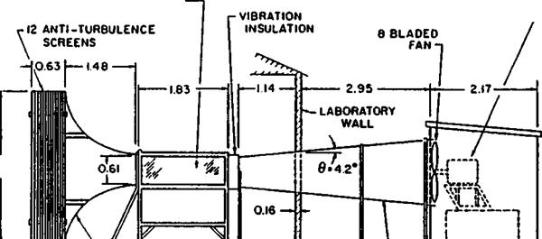
CONTRACTION CONE 24:1—* |
![]()
![]()
![]()
 |
Fig. 10.1 A modern low speed research wind tunnel of the open return or Eiffel type at Notre Dame University, Indiana, USA.
Note bothintake and exit are sheltered. ALL DIMENSIONS ARE IN METRES.