Our heavyweight helicopter equal in the world does not have
In Rostov started production of the most load-lifting rotary-wing car The Russian holding «Helicopt[...]

Everything about aircrafts and helicopters. News and events in aviation worldwide. Civil, transportation, military helicopters and airplanes.

Everything about aircrafts and helicopters. News and events in aviation worldwide. Civil, transportation, military helicopters and airplanes.

Everything about aircrafts and helicopters. News and events in aviation worldwide. Civil, transportation, military helicopters and airplanes.

Everything about aircrafts and helicopters. News and events in aviation worldwide. Civil, transportation, military helicopters and airplanes.


In numerical computation, surfaces of discontinuity, such as mesh-size-change interfaces, are potential sources of spurious numerical waves. For this reason, it is necessary to add artificial selective damping in the buffer region of the interface. For points A and A’, the 7-point damping stencils discussed in Chapter 7 may be used. For points B or B’, C or C special damping stencils are needed.
Consider the x-momentum equation of the linearized Euler equations.
I + = °- (1216)
The discretized form of Eq. (12.16) at point C, including the artificial selective damping terms, is
where the damping stencil coefficients satisfy the symmetric condition d— = d, va is the artificial kinematic viscosity, and Ax is the mesh size at C.
Consider a single Fourier component of u, i. e., u = u.(t)elaiAx. Substitution into Eq. (12.17) yields
(—^ +••• =———– —2DC (a Ax) u, (12.18)
dtJc (Ax)2 V ‘
where the damping function DC(aAx) is given by
DC(aAx) = dC + 2 [dC cos(aAx) + dCcos(2a Ax) + dCcos(4a Ax)]. (12.19)
As in Chapter 7, it is required that there is no damping if u is a constant (or a Ax ^ 0). This leads to
3
dC + 2J2 dj = 0. (12.20)
j=1
The normalization condition is DC(n) = 1.0 or
dC + 2(-dC + dC + dC) = 1. (12.21)
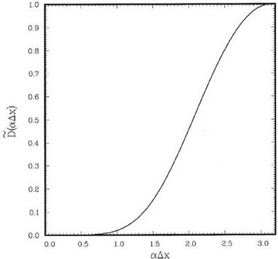
In addition, it is intended to select the remaining parameters such that Eq. (12.19) is a good approximation to a Gaussian function of half-width a centered at a Ax = n. Specifically, the integral
|
Figure 12.8. Damping function for stencil point C. к = 0.7, a = 0.2 n. |
is to be minimized. Numerical experiments suggest that a good choice of к and a are
к = 0.7, a = 0.2n. (12.22)
This yields the following damping stencil coefficients:
dCC = 0.350576727483
dC = d-1 = -0.25
dC = d-2 = 0.0788677598279
dC = d-3 = -0.004156123569. (12.23)
The damping function corresponding to this stencil is shown in Figure 12.8.
On following these steps, the coefficients of the damping stencil for points B or B’ are found. In this case, numerical experiments suggest the choice of к = 0.8 and a = 0.2n. The damping stencil coefficients are as follows:
dB = 0.5
dB = dB1 = -0.294977493296 dB = dB2 = 0.052389707989
dB = dB3 = -0.007412214693. (12.24)
The damping function is shown in Figure 12.9.
 |
|
One is often required to compute flows with a thin boundary layer adjacent to a wall. To calculate such rapidly changing flows, it is desirable to use higher spatial resolution in regions with rapid changes. Thus, the finest mesh is installed right next to the wall. In such a mesh design, one may have a cascade of mesh sizes through several layers from the outermost coarse layer to the finest mesh layer right at the wall. Experience has shown that it is possible for waves corresponding to grid-to-grid oscillations to be trapped in one of the nested mesh layers very close to the wall. This provides an environment for the growth of grid-to-grid oscillations as they bounce from one side of the layer to the other side, gaining amplitude at each reflection. It is, therefore, a good practice to impose stronger artificial selective damping in the computation for the fine meshes near a wall. For an estimate of the magnitude of mesh Reynolds number that should be imposed, it is noted that the time, T, needed by the short waves to propagate from one side of the mesh layer to the other side, is equal to the distance traveled divided by the speed of propagation. Here, the group velocity of the spurious grid-to-grid oscillations is taken to be approximately equal to twice the speed of sound a0 (see Figure 2.4). Hence, one finds
where N is the number of mesh points across the width of the mesh layer, and Ax is the mesh size. The total damping in this time period is given by Eq. (7.15). Since D (n) = 1.0, the total damping factor is
![]() _ _VL ____ N_
_ _VL ____ N_
e (Ax)2 = e 2Ra,
|
|
where RA=va/(Ax)a0 is the mesh Reynolds number. It is suggested that this factor should be equal to 10-2 or less to avoid accumulation of spurious grid-to-grid oscillations. On setting this factor equal to 10-2, a criterion for the choice of the mesh Reynolds number is established, namely,
N
— > 9.2. (12.27)
ra
For example, if the nested mesh layer has 20 mesh points, i. e., N = 20, then Ra1 > 0.46, say 0.5, should be used. This value is much larger than the value recommended for general background damping, which is Ra1 > 0.05. (Note: away from the solid boundaries a smaller and smaller inverse mesh Reynolds number should be used.) Formula (12.27) also suggests that any uniform mesh layer in a multisize-mesh computation should not have fewer than 20 mesh points. This is to avoid the necessity of using excessively large artificial damping.