Our heavyweight helicopter equal in the world does not have
In Rostov started production of the most load-lifting rotary-wing car The Russian holding «Helicopt[...]

Everything about aircrafts and helicopters. News and events in aviation worldwide. Civil, transportation, military helicopters and airplanes.

Everything about aircrafts and helicopters. News and events in aviation worldwide. Civil, transportation, military helicopters and airplanes.

Everything about aircrafts and helicopters. News and events in aviation worldwide. Civil, transportation, military helicopters and airplanes.

Everything about aircrafts and helicopters. News and events in aviation worldwide. Civil, transportation, military helicopters and airplanes.


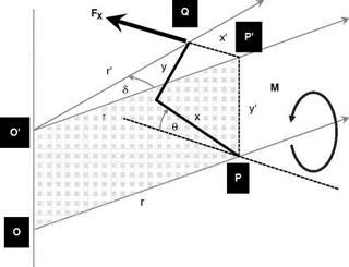
With reference to Figure 6.16, consider a point of a blade at Q. It is positioned on a blade section defined by the plane PP’Q and with a zero-pitch blade has the coordinates x (chordwise) and y
|
F
|
(thickness); however, the blade is rotated by an angle в and the position of Q can be defined by the coordinates x’ and y’.
Now Q will experience a centrifugal forcing term F in the direction shown in the figure. This will have a component, FX, in the direction normal to the radial line through P, the origin of the blade rotation. This will exert a moment about the axis OP in the direction of opposing the blade pitch rotation with a moment arm, y’. This is the propeller moment and is given by:
M = FX • y’ (6.1)
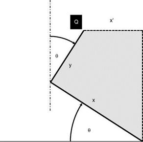
The forces F and FX are in a plane normal to the rotor shaft passing through the point Q. The transformation from (x, y) to (x’, y’) can be seen using Figure 6.17.
We therefore have the relations:
![]()
![]()
![]() x’ = x cos в—y sin в y’ = x sin в + y cos в
x’ = x cos в—y sin в y’ = x sin в + y cos в
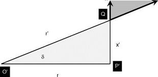
To evaluate the force component, FX, Figure 6.18 shows the plane O’P’Q. Now the centrifugal force F is given by:
F = O2r’ dm
where dm is the elemental mass of the blade at point Q.
Resolving gives:
FX = F sin d
|
![]()
|
|
|
|
|
whence the force component is given by:
FX = O2r0 dm • sin d = O2 dm • r’sin d = O2 dm • x’
and the elemental propeller moment now becomes:
dM = FX • і
= O2 dm • X • і
= O2 dm(x cos в—y sin 0)(x sin в + y cos в)
= O2 dm [(x2—y2)sin в cos в + xy(cos2 в—sin2 в)]
|
O2 dm |
![]()
![]() , 2 sin2в . .
, 2 sin2в . .
(x2—y2) + (xy) cos 2в
|
x2—y2) sin 2в + xy (cos 2в) |
|
x2 dm |
Finally, by integrating over the blade:
![]() y2 dm
y2 dm
BLADE
BLADE
If the tail rotor aerofoil is symmetric, the product of inertia, /XY, vanishes, whence (6.7) simplifies to:
1 о
Mprop = 2O (/XX — Iyy)sin20 (6.8)
To this is added the aerodynamic pitching moment giving:
1 2
Mtotal = 2O (/xx — /yy)sin 2У + Maero (6.9)
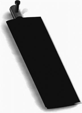
This pitching moment has to be reacted by the control system. For obvious reasons this has to be kept under limits of structural integrity and handling qualities – the pilot should not be expected to provide large forces on the pedals. The mechanism for adjusting the overall pitching moment is the bracketed term containing the difference of the two inertias. The moment can be increased by using /XX and decreased using /YY. Adjusting /XX is relatively easy since the blade layout is predominantly in the chordwise direction; however, /YY is not so easy as it can only be adjusted in the blade in the thickness direction, which is substantially lower because of the aerofoil section. To allow for this, the value of /YY is varied by means of an external mass added to the blade construction. It is usually mounted on the blade cuff as shown in Figure 6.19. These are termed preponderance weights.
|
|
|
|
|
|
|
|
|
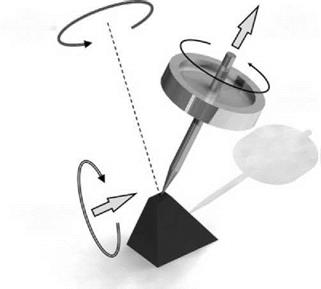
Figure 6.20 Precessing top