
Our heavyweight helicopter equal in the world does not have
In Rostov started production of the most load-lifting rotary-wing car The Russian holding «Helicopt[...]

Everything about aircrafts and helicopters. News and events in aviation worldwide. Civil, transportation, military helicopters and airplanes.

Everything about aircrafts and helicopters. News and events in aviation worldwide. Civil, transportation, military helicopters and airplanes.

Everything about aircrafts and helicopters. News and events in aviation worldwide. Civil, transportation, military helicopters and airplanes.

Everything about aircrafts and helicopters. News and events in aviation worldwide. Civil, transportation, military helicopters and airplanes.


3.6.1 Force Prediction for a Pitching and Plunging Airfoil in Forward Flight
It was in the early 20th century that the aerodynamic force generation on a moving airfoil was treated using the linearized aerodynamic theories. Wagner [329]
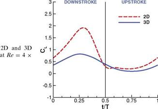 Figure 3.46. Lift coefficient for the (AR = 2) flat plates in shallow stall 104. From Kang et al. [324].
1
|
0.75-
0.25 |
![]()
![]()
![]() 0
0
-1 -0.5 0 0.5 1
x3
1
0.75- 0.25-
0
-1 -0.5 0 0.5 1
xl
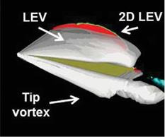
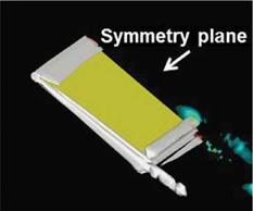
(a) iso-Q-surface at Q = 4 (white) and Q (b) spanwise lift distribution due to pressure. t/T
contours from the 2D computations on the Red dot: 2D; Blue solid: 3D.
symmetry plane.
Figure 3.47. Iso-Q surfaces (a) and spanwise lift distribution (b) to illustrate the difference in the flow structures at the center of the downstroke (t/T = 0.25) and the center of upstroke (t/T = 0.75). From Kang et al. [324].
calculated the lift generation on a thin airfoil moving impulsively from rest to a uniform velocity in a 2D incompressible fluid. Vortex wake generated due to the motion of the airfoil affects the force acting on the airfoil. Half of the final lift is generated at the beginning of the motion, and the instantaneous lift asymptotically approaches its final value as a function of increasing time. For harmonically pitching and plunging thin airfoils, Theodorsen [330] derived an expression for the lift by assuming a planar wake and a trailing-edge Kutta condition in incompressible inviscid flow; see Eq. (3-21):
^ _ , nc a h c(2xp — 1)a
Cl (t) = 2П(1 — C{k))a° + ~2 TH + m — 2U2
![]() + 2n C(k) и + a + c(1-5 — 7xv) —
+ 2n C(k) и + a + c(1-5 — 7xv) —
The pitch and plunge motions are described by the complex exponentials, a(t) = a0 + aae(2n ft+V)i andh(t) = hae2n fti. The phase lead of pitch compared to plunge is denoted by f. C(k) is the complex-valued Theodorsen function with magnitude < 1; it accounts for the attenuation of lift amplitude and the time lag in lift response from its real and imaginary parts, respectively. The first term is the steady-state lift, and the second term is the non-circulatory lift due to acceleration effects. The third term models circulatory effects. The same expressions were obtained by Kiissner [331] and von Karman and Sears [332].
For a harmonically plunging thin rigid flat plate in a free-stream, the lift coefficient can be derived assuming inviscid incompressible flow (see Eq. (5-347) as in Bisplinghoff, Ashley, and Halfman [333]):
CL = 2n2St k cos(2n ft) + 4n2 St sin(2n ft), (3-22)
assuming quasi steady-state flow where the influence of the wake vorticities is neglected. The first term in Eq. (3-22) is the non-circulatory term that is consistent with the added mass force derived in Section 3.6.4. The second term in Eq. (3-22) is the circulatory term, which can be expressed in a more familiar form, 2nae, by recognizing that 2nSt sin(2n ft) & ae where ae is the effective AoA for purely plunging motions. Note also that Eq. (3-22) is a simplification of Eq. (3-21) for purely plunging motion with C(k) = 1 equivalent to k ^ 0.
Based on the formulas derived by Theodorsen for the lift and the work by Karman and Burgers [334], Garrick [335] investigated the thrust generation by a harmonically pitching and plunging thin airfoil in uniform free-stream. For a special case of a pure plunge motion the thrust generation CT was
CT = n2 St2 (F2 + G2), (3-23)
where F(k) and G(k) are the real and the imaginary parts, respectively, of the Theodorsen function C(k) – see Eq. (3-21) – predicting greater thrust for higher Strouhal numbers. For a NACA 0012 airfoil Heathcote and Gursul [336] compared the experimentally measured thrust generation with Garrick’s formula [335] and used numerical computation to solve the Navier-Stokes equations [337]. It was shown that Garrick’s formula overestimates the experimentally measured thrust, which is in good agreement with the Navier-Stokes computations.


