Laser-Doppler anemometer (LDA)
4.1.1 The Doppler effect
The laser-Doppler anemometer, invented in 1964 by Yeh and Cummins, is a tool that allows the measurement of the velocity of a particle from the difference in frequency between the light that strikes the moving particle and that is scattered and seen by an observer (Doppler effect).
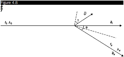
Consider a particle that moves with speed U and is hit by a laser beam of wavelength 10 and frequency f0 = c/10 (Figure 4.8). Denote with e the unit vector corresponding to the direction of propagation of the incident beam. The light is scattered by the particle in all directions (Figure 4.1). Consider the light scattered along the unit vector es, the frequency of this radiation is fs and the wavelength 1s, the Doppler effect is the difference in frequency fS – f0.
The speed of the wave fronts of the incident beam with respect to the particle is
c-U ■eI
thus, the frequency with which the wave fronts are intercepted by the particle is:
 |
Schematic representation of the Doppler effect
 |
|
The light re-emitted by the particle has the frequency f and the wavelength A _ c/f. A fixed observer, who receives the light scattered in the direction es, will intercept the wave fronts with the frequency:
From Equation (4.2), taking account of Equation (4.1):
Since 1S И l, then A A = A):
f _ fo +-y–ei)
A)
The difference in frequency due to the Doppler effect is thus equal to
fD _ fs – fo _ U• ( – A) (4.3)
A)
Recalling the meaning of the difference of two unit vectors, Equation (4.3) can be interpreted by saying that the detected Doppler frequency is proportional to the velocity component in the direction normal to the bisector of the angle в formed by the laser beam with the direction of observation:
r 0 • (вЛ Ucosy
fD _ 2s’“ll)— (4’4)
where у is the angle, unknown, formed by the velocity vector with the normal to the bisector of the angle в.
The benefits for an instrument which works on this principle are many:
■ It requires no calibration.
■ Measurements are made without disturbing the flow.
■ A velocity component can be measured in any desired direction (in the case of 2-D and 3-D flow fields, the resultant velocity vector can be obtained by, respectively, two or three measured components).
![]()
![]()
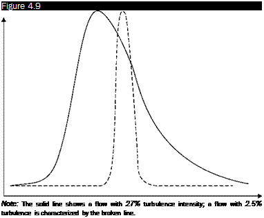
If the flow is turbulent, it is necessary to measure the speed of a large number, n, of particles and report its statistical distribution (Figure 4.9), it is possible to obtain the average velocity, Ucosy and the turbulence intensity, Tu, by calculating:
To measure a velocity component of a particle irradiated with a laser of known frequency, it should be sufficient to measure the frequency of the scattered light: this procedure is unfortunately impossible because it would be necessary to measure the effects on the frequency produced by the velocity of the particle (order 101 – r – 102 m/s) with respect to the speed of light (order 108 m/s) and so the measure would require
 |
Frequency histograms
Number of Events
a tool with a sensitivity of 10-6 – r – 10-7. The LDA must therefore rely upon a system able to measure the Doppler frequency, fD directly. This can be done by overlapping two electromagnetic waves with electric vectors
E = E (cos a + isin a1) E2 = E2 (cos a2 + isin a2)
where a = 2nft = 2’nct = 2n^ and I is the optical path; by indicating
Я Я ’
the intensity of waves with/1 = E and I2 = E^the intensity IU2 of the resulting wave is:
I1+2 = I1 + I2 + 2//"/~cos(a2 – a1) (4.5)
The resultant light intensity is thus composed of a continuous part and an alternative part that is proportional to the difference of the frequencies of the incident rays, linked in some way to the speed of the particle, in the case of LDA.


