Variable camber sections
Lifting wings need mechanical control devices to vary their effective camber Geometrical definition of simple hinged and deflected leading and trailing edges arc defined by airfoil chord wise hinge locations and deflection angles. A more sophisticated mechanical flow control includes clastic surface components to ensure a certain surface smoothness across the hinge, such devices are called sealed slats and flaps (Figure 57). Spline portions or other analytical connection fits may suitably model any proposed mechanical device, an additional parameter is the chord portion needed for the elastic scaling
Multicomponent airfoils
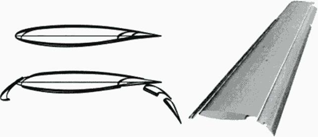
While sealed flaps and slats arc suitable for supersonic w ings, the much more complicated multicomponent high lift sy stems have been developed for current subsonic transport aircraft In addition to angular deflection of slat and flap components, they require kinematic shifting devices housed within flap track fairings below the wing. For a mathematical and parameter-controlled description of slat and flap section geometries w ithin the clean airfoil, the richness of our function catalog provides suitable shapes and track curves for a realistic modelling of these components in every phase of start and landing configurations. Figure 58 illustrates a multicomponent tugh lift system in 2D and 3D.

|
|
|


