Axially defined components
Fuselage bodies, nacelles, propulsion ami tunnel geometries
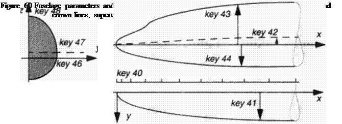
This group of shapes is basically aligned w ith the main flow direction, the usual development is directed toward creating volume for payload, propulsion or. in internal aerodynamics (and hydrodynamics) the development of channel and pipe geometries. The parameters of cross sections arc quite different to those of airfoils: the quality of their change along a mam axis with constraints for given areas w ithin the usually symmetrical contour is the design challenge. Fuselages are therefore described by another set of “keys” which is defined along the axis. This axis may be a curve in 3D space, with available gradients providing cross section planes normal to the axis. For simple straight axes in the cartesian x-dircction key 40 defines axial stations just like key 20 defines spanwisc x-siations. With the simplest cross section consisting of supercllip – tic quarters allowing a choice of the half axes or crown lines and body pUnform. plus the expo-
 |
nents ( with the value of 2. for ellipses). 8 parameters (key 41 – 48) arc given (Figure 60). Basic bodies are described easily this way. with either explicitly calculating the horizontal coordinate y(x, z) for given vertical coordinate z, or the vertical upper and lower coordinate z(x. y) for given points у within the planform. at each cross section station x • const.
More complex bodies arc defined by optional other shape definition subprograms with additional keys (49 – 59) needed for geometric details. These may be of various kind but of paramount interest is the aerodynanucally optimized shape definition of wing-body junctures. In the following a simple projection technique is applied requiring only a suitable wing root geometry to be shifted toward the body, but more complex junctures require also body surface details to suitably meet the wing geometry.


