Our heavyweight helicopter equal in the world does not have
In Rostov started production of the most load-lifting rotary-wing car The Russian holding «Helicopt[...]

Everything about aircrafts and helicopters. News and events in aviation worldwide. Civil, transportation, military helicopters and airplanes.

Everything about aircrafts and helicopters. News and events in aviation worldwide. Civil, transportation, military helicopters and airplanes.

Everything about aircrafts and helicopters. News and events in aviation worldwide. Civil, transportation, military helicopters and airplanes.

Everything about aircrafts and helicopters. News and events in aviation worldwide. Civil, transportation, military helicopters and airplanes.


Postprocessing of CFD results with a powerful graphic system (117) shows detailed display of flow vanables distribution along the configuration and in the flow field. Selected cross section pressure checks allow for an assessment of chosen airfoils and twist distributions before refined gnds and longer Euler or Navier-Stokes runs are executed. Though areas of necessary
local grid refinement arc spotted, some basic information about needed airfoil changes is already provided by such short runs; the refinement of geometry and CFD analysis may begin.
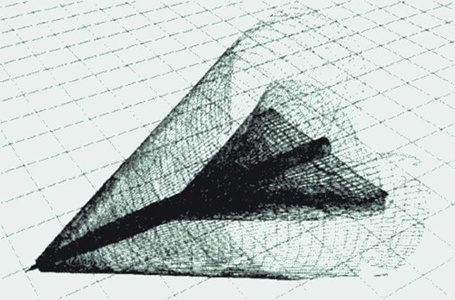
Visualization of the shock waves system emanating from the body tip and the wing is shown in Figure 65. A new visualization technique (125j allows for analyzing shock waves found by CFD analysis in 3D space: their quality near the aircraft, as shown, or with refined CFD analysis in larger distances to investigate sonic boom propagation, may be a useful help to assess this environmentally important aspect of supersonic transport. The figure shows a cut-off domain of the shock surfaces: A shock strength threshold allows analysis of local sonic boom quantities.
|
Figure 65 Visualization of CFD results: Shock system emanating from body tip and wing root, cut-off at threshold for selected sonk boom strength. |