Our heavyweight helicopter equal in the world does not have
In Rostov started production of the most load-lifting rotary-wing car The Russian holding «Helicopt[...]

Everything about aircrafts and helicopters. News and events in aviation worldwide. Civil, transportation, military helicopters and airplanes.

Everything about aircrafts and helicopters. News and events in aviation worldwide. Civil, transportation, military helicopters and airplanes.

Everything about aircrafts and helicopters. News and events in aviation worldwide. Civil, transportation, military helicopters and airplanes.

Everything about aircrafts and helicopters. News and events in aviation worldwide. Civil, transportation, military helicopters and airplanes.


The flap at the trailing edge of an aerofoil is essentially a high-lifting device, which when deflected down causes increase of lift, essentially by increasing the camber of the profile. The thin aerofoil discussed in the previous sections of this chapter can readily be applied to aerofoils with variable camber such as flapped aerofoils. It has been found that the circulation distribution along the camber line for the general aerofoil can comfortably be split into the circulation due to a flat plate at an incidence and the circulation due to the camber line.
It is sufficient for the assumptions in the theory to consider the influence of a flap deflection as an addition to the above two components. Figure 6.8 illustrates how the three contributions to lift generation can be combined to get the resultant effect.
‘ n
![]()
 U
U
(a)
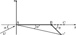
Indeed the deflection of the flap about a hinge in the camber line effectively alters the camber of the profile so that the contribution due to flap deflection is an addition to the effect of the camber line shape. In this manner, the problem of a cambered aerofoil with flap is reduced to the general case of fitting a camber line made up of the chord of the aerofoil and the flap deflected through an angle n, as shown in Figure 6.9.
The thin aerofoil theory stipulates that the slope of the aerofoil surface is small and that the displacement from the x-axis is small. In other words, the leading and/or trailing edges need not be on the x-axis.
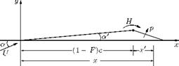
Let us define the camber as hc so that the slope of the part AB of the aerofoil is zero, and the slope of the flap h/F. To find the coefficient of the circulation к for the flap camber, let us substitute these values of slope in Equations (6.32) and (6.34) but confining the limits of integration to the parts of the aerofoil over which the slopes occur. Thus:
![]() ф
ф
where ф is the value of Є at the hinge, that is:
(1 — F) c = 2 (1 — cos ф) ,
hence cos ф = 2F — 1. Integrating Equation (6.39), we get:
ф
A0 = a + n——- (n),
![]()
|
that is:
|
|
|
|
|
|
|
|
Similarly, from Equation (6.34):
|
|||
|
|
||
|
|||
This gives:
|
|
|
|
Thus:
2 sin ф sin 2ф
A1 — ——— n and A 2 —————- n.
The chordwise circulation distribution due to flap deflection becomes:
![]()
2л Aq + л Aj
giving:
![]() Cl — 2л a + 2(л — ф + sin ф) n.
Cl — 2л a + 2(л — ф + sin ф) n.
Likewise, the pitching moment coefficient CMle from Equation (6.36) is:
that is:
In Equations (6.43) and (6.44) ф is given by:
•(1 — F) — ^ (1 — cos ф).
![]()
|
Note that a positive (that is, downward) deflection of the flap decreases the moment coefficient, tending to pitch the aerofoil nose down and vice versa.