
Our heavyweight helicopter equal in the world does not have
In Rostov started production of the most load-lifting rotary-wing car The Russian holding «Helicopt[...]

Everything about aircrafts and helicopters. News and events in aviation worldwide. Civil, transportation, military helicopters and airplanes.

Everything about aircrafts and helicopters. News and events in aviation worldwide. Civil, transportation, military helicopters and airplanes.

Everything about aircrafts and helicopters. News and events in aviation worldwide. Civil, transportation, military helicopters and airplanes.

Everything about aircrafts and helicopters. News and events in aviation worldwide. Civil, transportation, military helicopters and airplanes.


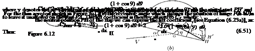
Let us consider an aerofoil whose rear part is movable about a hinge at P on the camber line, as shown in Figure 6.12(a). Essentially the rear part PH is the flap, which can be raised or lowered from the neutral position shown in the figure.
In an aerofoil of finite aspect ratio, the flap movement affects only part of a wing. Ailerons are flaps near the wing tips and are arranged so that the port and starboard ailerons move in opposite senses (that is, one up and one down). In our discussions here let us consider a two-dimensional problem for simplicity and assume that the aerofoil is thin, and the portion PH of the camber line is straight, and the angle § through which the flap is rotated is small.
Thus the effect of raising the flap is to decrease the lift coefficient, the effect of lowering the flap is to increase the lift coefficient. Therefore, in particular, when the flaps are lowered just before landing, increased lift is obtained (and also increased drag). In the case of ailerons, if the port aileron is raised and the starboard aileron depressed, the lift on the port wing is decreased and that on the starboard wing is increased, causing a rolling moment which tends to raise the starboard wing tip.
6.4 Summary
The overall lifting property of a two-dimensional aerofoil depends on the circulation it generates and this, for the far-field or overall effects, has been assumed to be concentrated at a point within the aerofoil profile, and to have a magnitude related to the incidence, camber and thickness of the aerofoil.
The loading on the aerofoil, or the chordwise pressure distribution, follows as a consequence of the parameters, namely the incidence, camber and thickness. But the camber and thickness imply a characteristic shape which depends in turn on the conformal transformation function and the basic flow to which it is applied.
The profiles obtained with Joukowski transformation do not lend themselves to modern aerofoil design. However, Joukowski transformation is of direct use in aerofoil design. It introduces some features which are the basis to any aerofoil theory, such as (a) the lift generated by an aerofoil is proportional to the circulation around the aerofoil profile, L а Г. (b) The magnitude of the circulation Г must be such that
it keeps the velocity finite in the vicinity of trailing edge. It is not necessary to concentrate the circulation in a single vortex, the vorticity can be distributed throughout the region surrounded by the aerofoil profile in such a way that the sum of the distributed vorticity equals that of the original model, and the vorticity at the trailing edge is zero. This mathematical model may be simplified by distributing the vortices on the camber line and disregarding the effect of thickness. In this form it becomes the basis for the classical “thin aerofoil theory” of Munk and Glauert.
The usefulness or advantage of the theory lies in the fact that the aerofoil characteristics could be quoted in terms of the coefficient Ax, which in turn could be found by graphical integration method from any camber line.
General thin aerofoil theory is based on the assumption the aerofoil is thin so that its shape is effectively that of its camber line and the camber line shape deviates only slightly from the chord line.
The camber line is replaced by a line of variable vorticity so that the total circulation about the chord is the sum of the vortex elements. Thus, the circulation around the camber becomes:
Г = f kSs.
J0
The lift per unit span is given by:
c
L = pUr = pU kdx.
0
Again for unit span, the moment of pressure forces about the leading edge is:
г г
Mle = — pxdx = —pU kx dx.
00
For a flat plate, dy/dx = 0. Therefore, the general equation [Equation (6.9)] simplifies to:
1 fc kdx
![]() Ua =
Ua =
The elementary circulation at any point on the flat plate is:
Lift per unit span is given by:
![]() L = 1 pU2(c x 1)C
L = 1 pU2(c x 1)C
The lift coefficient CL becomes:
The pitching moment per unit span is:
—Mie = 2 pU2 c2a 1(—Cmu).
The pitching moment coefficient becomes:
For small values of angle of attack, a, the center of pressure coefficient, kcp, (defined as the ratio of the center of pressure from the leading edge of the chord to the length is chord), is given by:
This shows that the center of pressure, which is a fixed point, coincides with the aerodynamic center. This is true for any symmetrical aerofoil section.
The center of pressure is at the quarter-chord point for a symmetrical aerofoil.
By definition the point on the aerofoil where the moments are independent of angle of attack is called the aerodynamic center. The point from the leading edge of the aerofoil at which the resultant pressure acts is called the center of pressure. In other words, center of pressure is the point where line of action of the lift L meets the chord. Thus the position of the center of pressure depends on the particular choice of chord.
The center of pressure coefficient is defined as the ratio of the center of pressure from the leading edge of the aerofoil to the length of chord.
The moment about the quarter-chord point is zero for all values of a. Hence, for a symmetrical aerofoil, we have the theoretical result that “the quarter-chord point is both the center of pressure and the aerodynamic center.”
The aerodynamic center is located around the quarter chord point. Whereas the center of pressure is a moving point, strongly influenced by the angle of attack.
Center of pressure is the point at which the pressure distribution can be considered to act – analogous to the “center of gravity” as the point at which the force of gravity can be considered to act.
The horizontal position of the center of gravity has a great effect on the static stability of the wing, and hence, the static stability of the entire aircraft. If the center of gravity is sufficiently forward of the aerodynamic center, then the aircraft is statically stable. If the center of gravity of the aircraft is moved toward the tail sufficiently, there is a point – the neutral point – where the moment curve becomes horizontal; this aircraft is neutrally stable. If the center of gravity is moved farther back, the moment curve has positive slope, and the aircraft is longitudinally unstable.
For a circular arc aerofoil at an angle of attack a to the flow k can be expressed as:
The effect of camber is to increase k distribution by (2U x 2ft sin в) over that of the flat plate. Thus:
k — ka + kb,
where:
arises from the incidence of the aerofoil alone and:
which is due to the effect of the camber alone.
The lift L acting on the aerofoil can be expressed as:
L = I pU 2c 2n(a + 0)
Cl = 2п(а + в) •
Thus the lift-curve slope is:
From the above relations for Cl and dCL /da, it is evident that:
at a = 0, Cl = 2пв at a = —в, Cl = 0
and the lift-curve slope is independent of camber.
For a cambered aerofoil, we have:
![]() 2n (a + в)
2n (a + в)
![]() dCL,
dCL,
-da(a
For Cl = 0, a = —в or —aL=0 = в. Thus:
The pitching moment is:
Mie = —2pU2c2 ^(a + 2в) • Therefore, the pitching moment coefficient becomes:
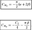 or
or
The center of pressure coefficient, kcp, becomes:
Thus, the effect of camber is to set back the center of pressure by an amount which decreases with increasing incidence or lift.
The general camber line can be replaced by a chordwise distribution of circulation. That is:
k = ka + kb,
where
Note that this ka distribution satisfies the Kutta-Joukowski distribution, since ka = 0 when в = n, that is, at x = c.
The corresponding kb is represented by a Fourier series. Providing 0 < в < n, the end conditions are satisfied, and any variation in shape is accommodated if it is a sine series. Thus:
kb = 2U (Aj sin в + A2 sin 2в + A3 sin 3в + •• ••)
TO
= 2U ^ ‘ An sin пв.
1
Thus, k = ka + kb becomes:
The coefficients A0, A1, A2, • • ••, An can be obtained by substituting for k in the general equation (6.30), suitably converted with regard to units.
For a thin aerofoil, the circulation distribution is:
The lift is also given by:
1 2
L = – pU 2cCL.
Therefore, the lift coefficient becomes:
The pitching moment is given by:
-Mie = ~CMle-xPU c.
The pitching moment coefficient is:
The center of pressure coefficient is:
Flap at the trailing edge of an aerofoil is a high-lifting device, which when deflected down causes increase of lift, essentially by increasing the camber of the profile. The deflection of the flap about a hinge in the camber line effectively alters the camber of the profile so that the contribution due to flap deflection is an addition to the effect of camber line shape.
The chordwise circulation distribution due to flap deflection becomes:
The lift coefficient is:
CL = 2л a + 2(л — ф + sin ф) n.
Likewise, the pitching moment coefficient CMe is:
л l r, , 1
Cmu =—2 a — 2 П — ф + sin ф (2 — cos ф)] n.
The characteristic of a flapped aerofoil, which is of great importance in stability and control of the aircraft, is the aerodynamic moment about the hinge line, H:
H = Ch 2 pU 2(Fc)2.
In an aerofoil of finite aspect ratio, the flap movement affects only part of a wing. Ailerons are flaps near the wing tips and are arranged so that the port and starboard ailerons move in opposite senses (that is, one up and one down). The effect of raising the flap is to decrease the lift coefficient, the effect of lowering the flap is to increase the lift coefficient. Therefore, in particular, when the flaps are lowered just before landing, increased lift is obtained (and also increased drag). In the case of ailerons, if the port aileron is raised and the starboard aileron depressed, the lift on the port wing is decreased and that on the starboard wing is increased, causing a rolling moment which tends to raise the starboard wing tip.
Exercise Problems
1. Determine the maximum circulation due to camber of a circular arc aerofoil of percentage camber 0.05, in a flow of velocity 200 km/h.
[Answer: 0.2224 m2/s]
2. If the lift coefficient and lift curve slope of an aerofoil of percentage camber 0.6 are l.02 and 2, respectively, determine (a) the pitching moment about the leading edge and (b) the center ofpressure coefficient.
[Answer: (a) —0.254, (b) 0.2685]
3. If the elemental circulation at 30% chord of a flat plate in a flow at 40 m/s is 24 m2/s, determine the angle of attack.
[Answer: 11.25° ]
4. A two-dimensional wing of NACA 4412 profile flies at an incidence of 4°. Determine the lift coefficient of the wing.
[Answer: 1.024]
5. An aerofoil of average chord 1.2 m, at an angle of attack 2° to a flow at 45 m/s at sea level, experiences a lift of 500 N per unit area. Determine the pitching moment about the leading edge, (a) assuming the profile to be symmetrical and (b) assuming the profile is cambered with 3% camber.
[Answer: (a) -178.6 N-m, (b) -434 N-m]
6. A Joukowski profile of 3.3% camber is in an air stream of speed 60 m/s at an angle of attack of 4°. Determine the circulation around the maximum thickness location.
[Answer: 28.22 m2/s]
7. A parabolic camber line of unit chord length is at an incidence of 3° in a uniform flow of velocity 20 m/s. If the camber line is given by: determine the velocity induced at the mid-chord location, assuming the incidence as an ideal angle of attack.
[Answer: -3.14 m/s]
8. An aircraft of wing area 42 m2 and mean chord 3 m flies at 120 m/s at an altitude where the density is 0.905 kg/m3. The center of pressure is at 0.28 times mean chord behind the leading edge of the wing when the wing lift coefficient is 0.2. (a) If the lift on the tail plane acts through a point 8 m horizontally behind the center of pressure, determine the tail lift required to trim the aircraft. (b) Assuming the wing profile as a circular arc, find the percentage camber. Assume the pitching moments on the tail plane, fuselage and nacelles are negligibly small.
[Answer: (a) 5201 N, (b) 0.191]
9. A thin aerofoil of 3% camber in a freestream has a lift coefficient of 1.2. (a) If the lift coefficient has to be increased by 10% of the initial value, what should be the increase in the angle of attack required? (b) Find the percentage change in the pitching moment coefficient caused by this change in the angle of attack.
[Answer: (a) 1.15°, (b) 7.88%]
10. A flat plate of length 1.2 m and width 1 m, in a uniform air stream of pressure 1 atm, temperature 30 °C and velocity 30 m/s, experiences a lift of 1500 N. Determine the lift coefficient, angle of attack, pitching moment about the leading edge and the location of center of pressure.
[Answer: CL = 2.384, a = 21.71°, CMle = —0.595, kcp = 0.25]
References
1. Spence, D. A., The lift coefficient of a thin, jet flapped wing, Proc. Roy. Soc. A., 1212, December 1956.
2. Spence, D. A., The lift on a thin aerofoil with jet augmented flap, Aeronautical Quarterly, August 1958.
![]()


