Complex Geometry
![]() Computationally, there are two general ways to treat problems with complex geometry. One way is to use unstructured grids. The other is to use overset grids. Overset grids are formed by overlapping structured grids. In this chapter, the basic idea of overset grids methodology and its implementation are discussed.
Computationally, there are two general ways to treat problems with complex geometry. One way is to use unstructured grids. The other is to use overset grids. Overset grids are formed by overlapping structured grids. In this chapter, the basic idea of overset grids methodology and its implementation are discussed.
13.1 Basic Concept of Overset Grids
To illustrate the basic idea of overset grids, consider the problem of computing the scattering of acoustic waves by a solid cylinder in two dimensions. In the space around the cylinder, the coordinates of choice for computing the solution is the cylindrical polar coordinates centered at the axis of the cylinder. This coordinate system provides a set of body-fitted coordinates and, hence, a body-fitted mesh when discretized around the cylinder. One significant advantage of using a body-fitted grid is the relative ease in enforcing the no-through-flow wall boundary condition using the ghost point method or other methods. Away from the cylinder, acoustic waves propagate with no preferred direction. The natural coordinate system to use is the Cartesian coordinates. Therefore, to take into account the advantages stated, one may use a polar mesh around the cylinder and a Cartesian mesh away from the cylinder with an overlapping mesh region. The overlapping mesh region is for data transfer from one set of grids to the other and vice versa.
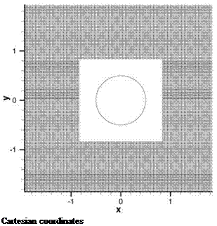
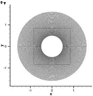
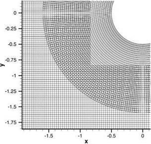
Figure 13.1 shows a Cartesian mesh with a square hole around the cylinder. For the purpose of putting all variables in dimensionless form, the diameter, D, of the cylinder is taken as length scale, speed of sound a0 as the velocity scale, D/a0 as the time scale, p0 (the density of the undisturbed gas) as the density scale, and p0a2 as the pressure scale. The mesh size is Ax = Ay = 1/32. The size of the square hole is 1.6 by 1.6. Figure 13.2 shows a polar mesh with Ar = 1/32 and Ав = n/150. The polar mesh extends to a distance of r = 1.5. The mesh overlap region is between the square and the outside edge of the polar mesh as shown in Figure 13.2. Figure 13.3 is an enlarged view of the mesh overlap region. Both the cylindrical mesh and the Cartesian mesh are structured meshes. To compute the solution, it would be best to write the governing equations in the coordinate system used. For acoustic wave scattering problems under discussion, the governing equations are the full Euler equations. In dimensionless form, they are

 |
||

 |
Figure 13.1. Cartesian grid used in acoustic wave scattering by a cylinder problem.
Figure 13.3. The overlapping region of the Cartesian and polar grids.
 Polar coordinates
 dp 1 d
— +——— (pvrr) + —
dt r 9r r r d0
9 vr 9 vr v- 9 vr v2 1 9p
—- + v—- + ———— —— + = 0
dt r 9r r d – r p 9r
9 v – 9 v – v – 9 v – vrv – 1 9 p
– + vr – + – – + r- – + = 0
dt r 9r r d0 r pd0
![]() 9 p 9 p vRd p (1 9 vrr 1 9 vfl 0
9 p 9 p vRd p (1 9 vrr 1 9 vfl 0
+ vr + – + Y p r + – = 0.
dt r 9r r d0 r 9r r d0
The solution of (13.1) is computed on the Cartesian mesh. The solution of (13.2) is computed on the polar mesh. (u, v) and (vr, v-) are related by
u = vr cos – – v – sin – v = vr sin – + v – cos – vr = u cos – + v sin-. v- = – u sin – + v cos –
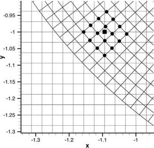
In computing the solution, the 7-point stencil dispersion-relation-preserving (DRP) scheme may be used. Since the 7-point stencil DRP scheme is a central difference scheme, the values of the computation variables of the three rows and columns of the Cartesian mesh around the square hole are not computed by the time marching scheme. They are found by interpolation from the values of the polar mesh using, say, a 16-point regular stencil. A typical stencil is shown in Figure 13.4. For the polar mesh, the values of the computation variables at the outer three rings are not computed. They are interpolated from the values of the Cartesian mesh using a 16-point regular stencil as shown in Figure 13.5.
Data transfer from one set of grids to the other is one of the crucial processes of the overset grids method. Since a high-resolution scheme is used for computation in each of the structured grids, it is important for the data transfer process to retain
Figure 13.4. Interpolation from a polar grid to a Cartesian grid using a 16-point stencil. Ax = Ay = Ar = 1/32, A0 = n/150.
 at least the same accuracy. In what follows, a highly accurate multidimensional interpolation scheme, suitable for use as a data transfer method, is discussed.


