Margins of Efficiency of PAR Based on a Reentrant Jet Scheme
The simple nonlinear one-dimensional theory of a rectangular wing with end – plates in the extreme ground effect, introduced in section 4, can be used together with PAR efficiency envelopes for qualitative prediction of the efficiency of power augmentation in a range of design parameters, including the adjusted pitch angle, the height of the endplates, the aspect ratio, and, the geometry of the lower surface of the wing. Simultaneously, such a mathematical model can be used as a tool for development of technical measures to enhance the performance of the vehicle both for power-augmented takeoff and cruise.
Taking into account these results, we can write the PAR efficiency and the thrust recovery fraction as
where the lift coefficient Cy and the drag coefficient Cx depend on the parameters G = 28ep/Xh = 25ep/A,[44] 9 = 6/h (6 the angle of pitch), = Sf/h, 8f the effective gap under the flap, en — єп//і, є the parameters of the form of the lower surface of the wing, Ct = Ct/h, and Cx = Cx/h. In the potential flow theory, the thrust coefficient and the width of the incoming jet are connected with each other as Ct = 2<Sj (or Ct = 2<Sj). The coefficients Cy and Cx can be determined by using the formulas of section 4, the latter without accounting for the suction force. Sets of curves corresponding to constant magnitudes of the thrust coefficient Ct and the effective gap of the flap 5f can be obtained from (8.148)-(8.149) by exclusion of Ct or respectively. The lower bound of the diagram is a straight line with the equation
(KPARh)mia = &)_ (1 – Tr). (8.150)
CX’ <5f=0
As seen from (8.150), the lower bound can be lifted if one manages to increase the lift-to-drag ratio of the wing in conditions of complete blockage of the flow under the flap (8f = 0). In the general case of a wing of finite aspect ratio, the upper bound of PAR efficiency in the scheme with a reentrant jet can be found through application of the momentum theorem and accounting for the mass conservation of incoming and escaping jets in the system. We adopt a general, though somewhat simplified, scheme of the interaction of jets due to power augmentation with the wing in the three-dimensional case, based on the PAR flow model with a reentrant jet. One should take into account that outgoing jets escape from under the rear flap and through the gaps under the tips of the endplates. Applying the momentum theorem in a projection onto the horizontal direction and rendering the resulting relationship nondimensional, we obtain
2A5j – 2A5Uj cos/?j – 2X5f – 2Iep = ACx, (8.151)
where Suj is the width of the reentrant jet,[45] and Iep is the lost momentum due to leakage through the gaps under the endplates. The momentum loss due to leakage can be determined by chordwise integration of the local momentum loss at cross sections x = const.:
і
Iep = 2 J vlp(x)6ep(x)dx (8.152)
о
or taking into account the relationship (4.51) between the velocity of the leakage vep(x) and the span-averaged velocity of the channel flow v(x) in the concrete case of a steady flow,
«ер = 1 – V2(x). (8.153)
We introduce the distribution of an effective gap under the endplates 5ep(^) = 5lpA(x), where, as earlier, <5ep is an effective gap under the endplates at the trailing edge and A{x) is a function of the order of unity that characterizes the form of this distribution. Taking into account the designation of parameter G = 25ep/h, we rewrite (8.152) as
і
/ep = hXG J [1 — v2(x)A(x) dx о
і
= hXG j p(x)A(x)dx = hGI*p, (8.154)
0
where h is the relative ground clearance, p(x) = l—v2(x) is the span-averaged pressure under the wing, and factor I* is determined by integration:
IeP= [ p{x)A(x)dx. (8.155)
Jo
In the particular case when the gap under the endplates is uniform chordwise, that is, A{x) = 1, the magnitude of Iep can be expressed in terms of the lift coefficient in the following way:
/ep = hXGCy. (8.156)
As a matter of fact, Iep represents the momentum drag and should be added to the drag coefficient Cx of the wing. Note, that in the PAR flow model, employing the scheme of a reentrant jet, the suction force is not realized.
To exclude the width of the jet escaping downstream £Uj from (8.151), we apply the requirement of mass conservation in the form
A<5j — A<SUj + A5f + 2Qep, (8.157)
where Qep is a nondimensional expression for the rate of air flow leaking through gaps under the endplates. This expression can be determined in the following way:
і
= ^ V^^)Sep(x)dx 0
l
= hGX I vW)A(x)dx=±hGQlp, (8.158)
0
Substituting (8.147) and (8.149) in (8.144), accounting for (8.150),
Setting /?j = 7Г, we obtain the equation of the upper boundary of the PAR efficiency diagram
|
c..,. = Mu. = Mt + і (c, + 2^ + 2^), Cx + 2hGI* |
|
Ct. lmm Cx + 2G(I*p + Q*ep) |
![]()
![]()
 |
||
(-^■PAR ^)max —
![]() C! L + 2C^£
C! L + 2C^£
Ct_._
where Ctmln = Ctmln/Mjmln = 5imJh, and Cx = Cx/h, and Цр and Q*p are calculated by using formulas (8.147) and (8.150).
It important to note that for fixed magnitudes of в and en characterizing the angle of pitch and the geometry of the channel between the wing and the ground, as well as for a given form of the endplate gap distribution, both the upper and lower bounds of the PAR efficiency envelopes depend on a similarity criterion G = 28ep/Xh. Both bounds of the diagram can be shown to move down with an increase in G. In its turn G increases with an increase in the relative gap under the endplates 5ep, a decrease in the aspect ratio A, and a decrease in the ground clearance h.
Figures 8.13-8.16 show some calculated results that illustrate the influence of different factors on PAR efficiency diagrams.
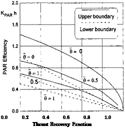
In particular, Fig. 8.13 presents the influence of parameter 0 (where 9 is measured in radians) for no leakage (5°p = 0). It can be seen that an increase of 9 leads to shifting of the PAR efficiency domain downward, so that for
 |
Ct
Fig. 8.13. The influence of the angle of pitch upon the PAR efficiency (zero gap under the endplates).
any given pair of magnitudes Ct, <5f, the efficiency of power augmentation diminishes.
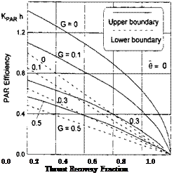
We turn to consideration of the influence of parameter G, which plays the role of an equivalent (generalized) gap under the endplates.[46] Just for simplicity of the analysis in these calculations, it was assumed that the effective gap under the endplates is constant chord wise A(x) = 1.
It follows from Figs. 8.14, plotted for a flat plate at zero incidence and a deflected flap, that augmentation of parameter G leads to a significant reduction of the PAR efficiency (the whole diagram drops down).
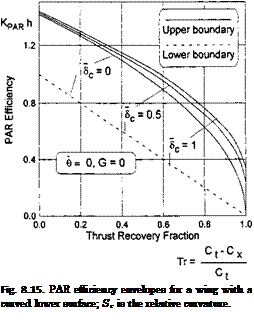
It is interesting to evaluate the influence of the curvature of the lower surface of the wing for в = 0 and a different G. It is seen from the PAR efficiency envelope (see Fig. 8.15) for a curved wing that an increase in the relative curvature Sc = Sc/h results in an increase in J^par^? especially in the range of larger magnitudes of the thrust recovery fraction. Similarly to a wing without curvature a nonzero gap under the endplates leads to reduction of the efficiency of blowing for a wing with endplates.
It is not difficult to explain a decrease in the PAR efficiency for a nonzero angle of pitch в > 0 and an improvement in efficiency for a wing curved upward. As the matter of fact, within the scheme of the reentrant jet an increase in the angle of pitch results in an increase in the pressure drag. At
 |
Ct
 |
Fig. 8.14. The influence of the endplate gap similarity parameter G = 5^/Xh upon the efficiency of the PAR regime.
the same time (at least for <5f not close to unity) the relative increment of Cy due to the angle of pitch is insignificant because the flow under the wing is already deccelerated due to the deflection of the flap.
Curving of the lower surface at a zero pitch angle (0 = 0), we can gain the same increment of lift as that of a flat wing with a nonzero pitch angle. At the same time, the corresponding pressure drag becomes much smaller the because horizontal component of the pressure force acting upon rear part of the wing is canceled by the pressure force (thrust) acting upon the forward part of the wing. Practically, because the vehicle normally has a certain (design) angle of pitch adjusted for cruise conditions, it is desirable, when using power augmentation at takeoff, to generate effects analogous to the action of curvature. This can be done by forward flaps.
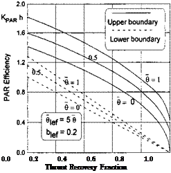
Figure 8.16 illustrates the influence of a forward flap upon the PAR efficiency of the wing in the extreme ground effect. In this example, the forward flap has a chord, constituting 20% of the wing’s root chord C0. Deflection of the flap was chosen to locate its leading edge tip at the level of or lower than the hinge of the rear flap. In the example under discussion, the former position is achieved for a flap deflection angle 9e = (1 — be)9/be. For example, when 9 = 2°, 9e should be not less than 8°.
 |
It follows from consideration of Fig. 8.16 that for nonzero angle of pitch and forward flap deflected downward, the efficiency of power augmentation increases for a given 9. If 9e > (1 — be)9/be, the efficiency domain shifts upward, so that the power augmentation efficiency becomes higher than that of a wing at zero incidence with a deflected rear flap. Essentially, this effect is due to the fact that, when the leading edge of the forward flap is lower
Ct
Fig. 8.16. PAR efficiency envelopes for a wing at an angle of pitch with a deflected forward flap (zero gap under the endplates).
than the hinge of the rear flap, the resulting pressure thrust reduces the total pressure drag of the wing.


