Linear Membrane Model
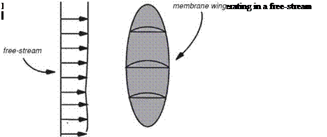
As an illustration, consider the membrane wing of Figure 4.12, which is shown operating in a free-stream. The analysis of membrane wings begins with the historical works of Voelz [421], Thwaites [422], and Nielsen [423]. These works consider the steady, 2D, irrotational flow over an inextensible membrane with slack. As a consequence of the inextensible assumption and the additional assumptions of small camber and incidence angle, the membrane wing boundary value problem is linearized and may be expressed compactly in non-dimensional integral equation form as
d2 (y/a)
![]()
 |
Ct f2 df2 d dy/a
2 0 2n(f – x) dx ’
where y(x) defines the membrane profile as a function of the x coordinate, a is the flow incidence angle, Ct is the tension coefficient, and f is the arc length along the membrane wing surface. Equation (4-2) was referred to as the “Thwaites sail equation” by Chambers [424] and simply as the “sail equation” by Greenhalgh et al. [425] and Newman [426]. This equation, together with a dimensionless geometric parameter є, completely defines the linearized theory of an inextensible membrane wing in a steady, inviscid flow field. Parameter є specifies the excess length of an initially flat and taut membrane and is defined as follows:
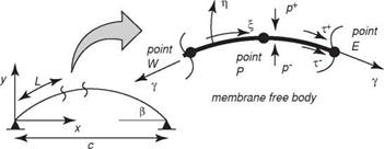
where L0 is the unstrained length of the membrane and c is the chord length. The meaning of these symbols can be better understood from Figure 4.13.
Different analytical and numerical procedures have been applied to the basic equation set to determine the membrane shape, aerodynamic properties, and membrane tension in terms of the AoA and excess length. In particular, Thwaites [422] obtained the eigensolutions of the sail equation that are associated with the wing at an ideal angle of incidence. Nielsen [423] obtained solutions to the same equation using a Fourier series approach that is valid for wings at angles of incidence other than the ideal angle. Other more recent but similar works are those by Greenhalgh
|
Figure 4.13. Leading edge constrained elastic membrane. |
et al. [425], Sugimoto and Sato [427], and Vanden-Broeck and Keller [428]. Various extensions of the linear theory have appeared in the literature over the years. Vanden-Broeck [429] and Murai and Maruyama [430] developed non-linear theories valid for large camber and incidence angle. The effect of elasticity has been included in the membrane wing theories of Jackson [431] and Sneyd [432], and Murata and Tanaka [433] investigated the effects of membrane porosity. In a paper by de Matteis and de Socio [434], experimentally determined separation points were used to modify the lifting potential flow problem in an attempt to model flow separation near the trailing edge. A comprehensive review of the work published before 1987 related to membrane wing aerodynamics is given by Newman [426].
The extent of agreement between the various potential flow-based membrane wing theories and experimental data has been reported by several authors, including Greenhalgh et al. [425], Sugimoto and Sato [427], and Newman and Low [141]. In general, there has been considerable discrepancy between the measurements made by different authors [431], which have all been in the turbulent flow regime at Reynolds numbers between 105 and 106. As a result of the discrepancies in the reported data, primarily due to differences in Reynolds number and experimental procedure, the agreement between the potential-based membrane theories and the data has been mixed. In particular, the measured lift is in fair agreement with the predicted value when the excess length ratio is less than 0.01 and the AoA is less than 5°. However, even for this restricted range of values, the measured tension is significantly less than that predicted by theory. Furthermore, for larger excess lengths and incidence angles the theory poorly predicts lift and tension.
The main reason for the disagreement is the existence of the viscous effect, which significantly affects the force distribution on the wing and therefore the effective shape of the wing. To illustrate the flexible structural dynamics in response to aerodynamic forces, consider equilibrium equations for a 2D elastic membrane subjected to both normal and shearing stresses. As discussed by Shyy et al. [417], the membrane is considered to be massless, and the equilibrium conditions are stated in terms of the instantaneous spatial Cartesian coordinates and the body – fitted curvilinear coordinates. The basic formulation is essentially identical to many previously published works such as de Matteis and de Socio [434] and Sneyd [432].
Figure 4.13 illustrates an elastic membrane restrained at the leading and trailing edges and subjected to both normal and tangential surface tractions p and т,
respectively. Imposing equilibrium in the normal and tangential directions requires that
![]() fy (dy2 3/2 = _Ap
fy (dy2 3/2 = _Ap
dx2 dx y
![]() (4-5)
(4-5)
where y is the membrane tension. Equation (4-4) is the Young-Laplace equation cast in Cartesian coordinates. The net pressure and shear stress acting on a segment of the membrane are given, respectively, by
|
> ^3 II 1 1 + |
(4-6) |
|
T = T — T + ■ |
(4-7) |
where the superscripts + and – indicate the values at the upper and lower surfaces of the membrane, as shown in the figure. If the membrane material is assumed to be linearly elastic, the nominal membrane tension Y may be written in terms of the nominal membrane strain S as
![]() Y = (S0 + ES)hs,
Y = (S0 + ES)hs,
where S0 is the membrane prestress, E is the elastic modulus, and hs is the membrane thickness. The nominal membrane strain is given by
S = L – Lo, (4-9)
Lo
where L0 is the unstrained length of the membrane and L is the length of the membrane after deformation, which may be expressed in terms of the spatial Cartesian coordinates as
![]() L=L 1+{%)dx■
L=L 1+{%)dx■
where c is the chord length.
The aeroelastic boundary value problem can be written in non-dimensional form after introducing the following dimensionless variables:
|
x x = ■ c |
(4-11) |
|
y=c |
(4-12) |
|
p _ p pUref q«> |
(4-13) |
|
Y h, 0r Y = Ehs ■ |
(4-14) |
|
P = |
where Eq. (4-14) is used to non-dimensionalize the membrane tension depending on whether the tension is dominated by pretension or by elastic strain. The resulting
dimensionless equilibrium equation when membrane tension is dominated by elastic strain is
![]() / 2 -3/2 d2f Л (df\ = __L AP
/ 2 -3/2 d2f Л (df\ = __L AP
dx*2 dx* П1 у * ’
with П1 the effective stiffness parameter, defined to be
When membrane tension is dominated by pretension, Eq. (4-4) leads to the following dimensionless equation:
![]() dV 1, (dy*2 -3/2 =_____________ L_ AP
dV 1, (dy*2 -3/2 =_____________ L_ AP
dx*2 dx* n1pret Y *
with the effective pretension, П1 t defined to be
If the two ends of a 2D membrane are fixed, the boundary conditions in dimensionless form are
![]() y* = 0 at x* = 0 and 1.
y* = 0 at x* = 0 and 1.
Regarding the physical significance of the aeroelastic parameters П1 and n1pret we note that the dimensionless deformation of an initially flat elastic membrane is inversely proportional to П1 in the absence of pretension. The dimensionless deformation of a membrane is inversely proportional to Щ ret in the presence of large initial pretension. Consequently, the steady-state, inviscid aeroelastic response of an initially flat membrane wing at a specified AoA is controlled exclusively by П1 in the limit of vanishing pretension, and exclusively by Щ ret in the limit of vanishing material stiffness. Similarly Song et al. [435] also presented a theoretical model for membrane camber due to aerodynamic loading and showed an expression for non-dimensional aerodynamic loading, expressed as a Weber number, We:
where в is the contact angles at the leading and trailing edges (Fig. 4.13).
This scaling analysis is based on a massless structure. If the airfoil mass is considered, then the inertia scaling needs to be considered. Between the elastic and inertia scaling, one can also deduce the structural natural frequency.


