Our heavyweight helicopter equal in the world does not have
In Rostov started production of the most load-lifting rotary-wing car The Russian holding «Helicopt[...]

Everything about aircrafts and helicopters. News and events in aviation worldwide. Civil, transportation, military helicopters and airplanes.

Everything about aircrafts and helicopters. News and events in aviation worldwide. Civil, transportation, military helicopters and airplanes.

Everything about aircrafts and helicopters. News and events in aviation worldwide. Civil, transportation, military helicopters and airplanes.

Everything about aircrafts and helicopters. News and events in aviation worldwide. Civil, transportation, military helicopters and airplanes.


The surface temperature of opaque bodies can be calculated by measuring the intensity of the emitted radiation which increases with the fourth
|
Spectrum of electromagnetic radiation
|
power of the body temperature. The range of wavelengths involved (Figure 5.5), l = 0.45 – r – 100 pm, goes from the visible, 0.45 – r – 0.75 pm (high temperatures), to the infrared (down to temperatures below ambient temperature).
This type of measurement overcomes some of the difficulties typical of diagnostic methods discussed in the previous paragraphs:
■ no alterations of the surface of the model is induced;
■ the sensitivity is in the order of tenth of K.
The relationship between the temperature of an object and the radiation received by the detector depends on the emissivity of the surface and on the absorption of the optical system: for each model and for each type of test, a prior calibration is therefore needed, for example, using thermocouples embedded in the surface of the model.
In the measurements with infrared camera, both optics and windows of the wind tunnels are critical because glass and quartz cannot be used, being both opaque to infrared radiation. Lenses are usually made of expensive germanium; cheaper materials quite transparent to infrared radiation are lucite, silicone and Domopak film.
The sensors used are indium antimonide (InSb), sprite (HgCdTe), lead selenide (PbSe), covering the field 2 – r – 13 pm: these are therefore suitable for measuring temperatures from 200 K to 2000 K (with appropriate filters). Since the sensitivity of these sensors increases when their operational temperature decreases, they should be kept at temperatures well below ambient. The different techniques used are:
■ cooling with liquid nitrogen at about 80 K; liquid nitrogen is difficult to maintain for a long time, not more than 2 hours, so the system is reserved for fixed installations in scientific laboratories;
■ cooling to 90 K by expansion of compressed argon (Joule-Thomson effect); the argon can be kept easily in cylinders and, unlike liquid nitrogen, its consumption is zero when the thermograph is not used;
■ cooling to 70 г 90 K with a Stirling pump which, in a closed circuit, compresses and expands helium; the circuit needs to be recharged only after a few thousand hours, the system is therefore suitable for field measurements;
■ cooling to 200 K with a thermoelectric (Peltier) circuit (thermocouple, in which a potential difference is applied and a temperature difference between junction and reference is obtained), the system is particularly suitable for surveillance cameras on a continuous basis.
If only one sensor is used, it is necessary to send on it in succession signals from each point of the field, i. e. a mechanical scanning of the image is needed. In Figure 5.6, an image of the field is produced by a spherical mirror of 200 mm diameter oscillating 16 times per second around a horizontal axis combined with a prism rotating at 400 revolution/second around a vertical axis; horizontal and vertical scanning, respectively, are performed in this way and the infrared radiation from each pixel is focused in turn on a single indium antimonide (InSb) sensor. The sensor converts thermal radiation into an electrical signal that is used to modulate the intensity of the beam of a cathode ray tube: the vertical position of the beam is synchronized with the position of the oscillating mirror and the horizontal position is synchronized with the rotating prism, each pixel of the field is thus transformed into a corresponding
![]() Schematic of AGA thermograph ThermoVision 750
Schematic of AGA thermograph ThermoVision 750
— Vertical sync, signal
— Horizontal sync, signal
![]()
 |
Cam
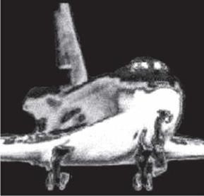
Thermographic image of a space shuttle in a hypersonic wind tunnel
|
|
pixel of the video screen. With this system, 16 images per second can be obtained.
To increase the frequency of images, multiple sensors can be used arranged in a row to eliminate the vertical scanning: with 10 – r – 30 sensors and a rotating polygon with 8 – r – 10 faces 30 images per second can be obtained. The most recent version of the camera provides in the focal plane of the objective a matrix of 320 x 240 uncooled microbolometer (768,00 pixels): 60 images per second are obtained. The resolution of the cameras is about 0.1 K, the error is of the order of 2% or 2 K (the larger of the two values).
The thermographic image of a model space shuttle in a hypersonic wind tunnel is shown in black and white in Figure 5.7.