Optimum Speeds
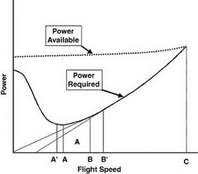
The bucket shape of the level flight power curve allows the ready definition of speeds for optimum efficiency and safety for a number of flight operations. These are illustrated in Figure 7.5. The minimum power speed (point A) allows the minimum rate of descent in autorotation. It is also, as discussed in the previous section, the speed for maximum rate of
|
|
climb, subject to a correction to lower speed (A0) if the parasite drag is increased appreciably by climbing. Subject to a further qualification, point A also defines the speed for maximum endurance or loiter time. Strictly the endurance relates directly to the rate of fuel usage, the curve of which, while closely similar to, is not an exact copy of the shaft power curve, owing to internal fuel consumption within the engine: the approximation is normally close enough to be acceptable.
Maximum glide distance in autorotative descent is achieved at speed B, defined by a tangent to the power curve from the origin. Here the ratio of power to speed is a minimum: the condition corresponds to that of gliding a fixed-wing aircraft at its maximum lift-to-drag ratio. Point B is also the speed for maximum range, subject to the fuel-flow qualification stated above. This is for the range in zero wind: in a headwind the best-range speed is at B0, obtained by striking the tangent from a point on the speed axis corresponding to the wind strength. Obviously, for a tailwind the tangent is taken from a point on the negative speed axis, leading to a lower best – range speed than B. This is discussed in more detail in the Appendix.


