The measurement of bandwidth
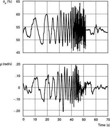
One of the failings of time domain criteria arises when trying to make accurate measurements of the rise times in the step response. While it is relatively easy and economical to apply a step input, the shapes of the rate and attitude response are very sensitive to the detailed form of the control input, and aircraft initial conditions. Errors in rise time computation, particularly for the smaller values (O(0.1 s)), can be large. Since the significant handling qualities parameter is actually the slope of the phase, any errors in rise time calculation will reflect in a poor estimation of the high frequency phase. On the other hand, the frequency response function is fairly robust to analysis, although considerably more calculation effort is required, and frequency response data are more difficult and far more time consuming to capture in flight test. Since the first publication of ADS-33 in the mid-1980s, considerable experience has been gained in the measurement of bandwidth and phase delay in flight (Refs 6.40-6.49). The recommended test input is a sine wave form with gradually increasing frequency applied at the pilot’s controls. Figure 6.34 illustrates a roll axis frequency ‘sweep’
|
Fig. 6.34 Roll axis frequency sweep for Bo105 (Ref. 6.43) |
showing the pilot’s control position and aircraft roll rate response for the Bo105 from a test speed of 80 knots. The test manoeuvre is complete in about 1 min, the pilot uses about 10-15% of the control range and the roll rate is contained within the range ±20o/s.
From the accumulated knowledge of frequency sweeping, a number of rules of thumb can be applied when designing and conducting a flight test. These concern both safety and performance aspects and are now addressed in turn.
(1) Frequency range The range of frequencies covered in the sweep need only be high enough to capture the phase characteristics up to twice the 180o phase lag frequency. Unfortunately, this latter frequency may not be known precisely prior to the test, and experience has shown that it can vary widely across different types, e. g., 22 rad/s on the Bo105 (Ref. 6.43) and 12 rad/s on the OH-58D (Refs 6.41, 6.42). Also, there may be only limited data available on the airframe/rotor structural modes within this frequency range. It is therefore very important to establish the upper frequency limit and the influence on structural modes very carefully with exploratory test inputs before applying a full frequency sweep. Reference 6.42 recommends a frequency range of 0.1-2 Hz, but clearly this is inadequate for higher bandwidth helicopters like the Bo105.
(2) Maintaining trim – instability One of the principal problems with the frequency sweeping of helicopters without stability augmentation is their natural tendency to diverge from the trim condition, particularly during the low-frequency portion of the sweep input. If this is allowed to happen, then clearly the validity of the data is questionable; the engineer can no longer relate the computed bandwidth to a particular flight condition, and nonlinear effects are likely to spoil the overall quality of the data. The pilot needs to apply ‘uncorrelated’ corrective inputs, superimposed on the sweep, to keep the aircraft manoeuvring about the trim condition. This can sometimes be very difficult if not impossible to accomplish satisfactorily, particularly close to hover or for pitch axis sweeps at high speed. In cases where the natural stability of the aircraft is so poor that frequency sweeping is not practicable, then it may well be necessary to deduce the open-loop, bare-airframe, characteristics from sweep results with the SCAS engaged.
(3) Cross-coupling While cross-coupling, in itself, is not a problem during frequency sweeping, it has become a practice for pilots to negate the cross-coupled motion with control inputs, primarily to preserve the mean trim condition. For example, the pitch and yaw moments generated during a roll sweep can soon give rise to large flight – path excursions. Even assuming the pilot is able to apply perfect cancelling inputs there are two data contamination effects that will need to be taken into account. First, the roll response will no longer be due to the lateral cyclic only, but there will be components at various frequencies due to the cross-control inputs. These can, in principle, be extracted using conditional frequency analysis (see below), effectively deriving the secondary frequency characteristics as well as the primary. Second, any correlation between the primary and secondary control inputs will make it very difficult to separate out the primary frequency response, even using the conditional techniques. As noted above, one solution is to apply corrective cross-coupled control inputs that are uncorrelated with the primary axis, e. g., occasional pulse-type inputs to recover airspeed, pitch attitude or sideslip.
(4) Control amplitude The magnitude of the control input is a compromise between achieving the highest signal-to-noise ratio to maximize the information content, and minimizing the excursions from trim and the potential for exciting dangerous loads. It has been found that there is a natural tendency for the inexperienced pilot to increase the control amplitudes as the frequency increases, in order to maintain the same overall amplitude of aircraft response. This should reduce with training (see point (7)). A general rule of thumb is that the control inputs should be kept to within ±10% of full control throw.
(5) Repeats Repeat runs are always required in flying qualities tests to ensure that at least one good data point is captured; for frequency sweeping, the recommended minimum number of repeats is two, to provide at least two quality runs for averaging in the frequency analysis.
(6) Duration The time duration of a frequency sweep depends on the frequency range to be covered, primarily the lower limit, and the rate of change of frequency. Assuming the latter to be about 0.1 Hz, experience has shown that sweep durations between 50 and 100 s are typical. Constraining factors will be the natural stability of the aircraft, influencing the time spent at low frequencies, and the rotor speed, largely influencing the upper limit.
(7) Training and practice One of the most important safety factors that can be included in a frequency sweep test programme is an adequate level of training for pilots. First, there is the simple matter of training pilots to apply a slowly varying sine wave with an amplitude of perhaps ±1 cm. Experience has shown that pilots new to sweeping tend to increase the amplitude of the controls as the frequency increases and they are not always aware that this is happening. Also, it is very difficult for a pilot to judge what is a 2-, 3- or 4-Hz input without experience. Ideally, the pilot would initiate his or her training by following through on the controls while the instructor applied the sweep with the aircraft on the ground. Sweeps on all controls could be taught this way to give the pilot a feel for the kind of hand and feet motion required. The pilot could then practice with a display providing feedback on the frequency and amplitude. After the trainee pilot is confident in his or her ability to apply the input shape, the training can continue in the simulator and eventually in flight, where the pilot needs to practice before the definitive inputs are made. Practising gives the pilot knowledge about what corrective inputs are required in other axes to maintain the aircraft close to the reference flight condition. Practising also allows the engineers conducting the structural loads monitoring to guide the trial better. But pilot-applied frequency sweeps are best done with two crew, one applying the input, the other calling the tune.
(8) Manual or automated inputs – it takes two to sweep In theory, it should be possible to design a frequency sweep for application through an automatic control input device that has superior properties to a manual input, e. g., repeatability, and better defined frequency content. However, the sweeping experience to date, especially with unstabilized helicopters, indicates that manual inputs are to be preferred, because of the increased flexibility in uncertain situations; and the more irregular shapes to the manual inputs actually have a richer information content. This situation has to improve in favour of the auto-inputs with time, but it should be remembered that the bandwidth frequency relates to the attitude response to the pilot’s stick input and not to the control servo input. With auto-inputs applied at the servo actuator, the additional transfer function between stick and servo would still need to be determined. Experience at the DRA with manual frequency sweeping has emphasized the value of the second crew member providing timing assistance to the pilot by counting out with rhythm, particularly at the lower frequencies. Counting out periods of 20, 16, 12, 8, 4 and 2 s helps the pilot to concentrate on applying a series of sine waves at increasing frequencies. At higher frequencies the pilot needs to rely on a learned technique, the counting then being a significant distraction.
(9) Load monitoring for structural resonances Frequency sweeping can damage a helicopter’s health and it is important to take this warning seriously. However, with the right preparations and precautions, the damage can be controlled and quantified. Some of the precautions have already been discussed under the headings of frequency range and amplitude, but it is important to know as much as possible about potential structural resonances before embarking on this kind of test input. In the case of a new aircraft, it is prudent to establish the rotor/fuselage coupled modes using the structural test development aircraft prior to making the bandwidth measurements. However, most of the testing carried out in the late 1980s was conducted on experimental aircraft, sometimes without a thorough analysis of potential resonances. Tests conducted by the US Army on the AH-64A and OH-58D (Ref. 6.42) revealed several potential problems. A divergent vertical bounce was experienced during longitudinal cyclic hover sweeps in the AH-64 at about 5 Hz. Damaged tail rotor support components were found following yaw axis sweeps, again on the AH-64. On the OH-58D, sweep tests excited an oscillation in the mast mounted sight, which was not felt by the crew, but only detected visually by the crew of the chase aircraft and through the telemetry at the ground station.
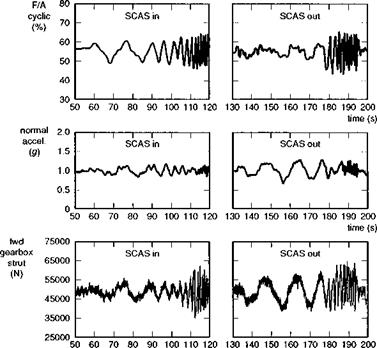
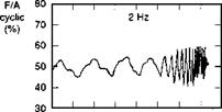
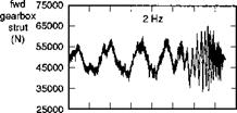
Earlier, at the Royal Aircraft Establishment, the first UK sweep tests were conducted with the research Puma fitted with a full fatigue usage monitoring strain gauge fit (Ref. 6.45). Higher fatigue usage was encountered in pitch axis sweeps in forward flight, and although we are still discussing the roll axis, the results are of such general significance in understanding the role of load monitoring that they are presented here. The tests were conducted to derive equivalent low-order system models for pitch axis dynamics (reported in Refs 6.28 and 6.45), but the test inputs were essentially the same as for the bandwidth measurement. Figure 6.35(a) illustrates two longitudinal cyclic frequency sweeps, one with the SCAS engaged, the other disengaged, captured at 60 knots airspeed. The additional data are the normal acceleration at the fuselage floor and the stress in the forward gearbox strut, derived from the component strain, which transpired to be the most critical for the pitch manoeuvre. The control input is maintained within the recommended range and the control frequency spectrum is primarily below 2 Hz, the required test upper limit. The larger response at the lower frequencies with the SCAS disengaged is noted. Figure 6.35(b) shows results at 100 knots, for two cases, one where the frequency range was limited to 2 Hz, the second where it was extended to 4 Hz. In the second case, the crew experienced significant vertical bounce at the higher end of the range. The normal acceleration record shows amplitude excursions of ±0.25 g at high frequency. A combination of real-time monitoring through a telemetry link to a ground station coupled with post-flight fatigue life accumulation analysis revealed the extent of the damage done during these tests. Figure 6.36 shows data for one flight (Flt No 728) comprising nine sweeps over the speed range 60-120 knots. The
|
|
|
|
|
|
|
|
|
|



![]()
Fig. 6.35 Longitudinal cyclic frequency sweeps on DRA research Puma: (a) 60 knots: SCAS on and off; (b) 100 knots: 2 Hz and 4 Hz
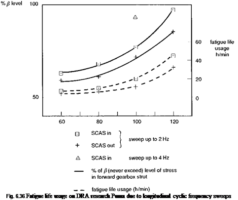
figure shows the percentage of the never-exceed fatigue load level, the so-called ^-level, in the forward gear box strut and the fatigue life usage across the speed range, for both SCAS-in and SCAS-out. A striking result is that the SCAS-out manoeuvres were less damaging than the SCAS-in manoeuvres. The SCAS-in sweep at 120 knots resulted in gearbox strut loads within 5% of the ^-level. The single triangle point at 100 knots corresponds to the case shown in Fig. 6.35(b), when the frequency range was extended to 4 Hz, again taking the load close to the limit. At the higher speeds, component life was being fatigued at the rate of more than 40 h/min. Following these tests, the calculation of the fatigue life used during flight 728 revealed that more than 11 h of life had been used in just nine sweeps. Accumulated life over the period of the tests indicated that the gearbox mounts were prematurely approaching their 2000-h limit. The aircraft was grounded while the gearbox mounts and other related components were replaced.
The lessons learned during these first few years of sweeping suggest that load monitoring, preferably in real time, is the safest precaution against undue structural damage. This requirement elevates the risk level associated with flying qualities testing, placing increased instrumentation demands on prototype aircraft. However, as will be discussed in the sections on subjective assessment in Chapter 7, flying
MTEs can also incur larger than usual fatigue life usage. The new approach to flying qualities criteria and test, epitomized by ADS-33, is clearly much more than just a new cookbook.
(10) Incrementally safe This final rule attempts to sum up the approach by emphasizing the importance to safety of engaging with frequency sweeping in an incremental manner, increasing frequency and amplitude only when confidence has been gained at lower values.
These ten rules have been laboured because of the novelty and the safety implications associated with frequency sweeping and because of the lack of guidance in the open literature. A frequency sweep is a flying qualities test but it shares many of the same characteristics as a loads test. Indeed, it might be argued that a rotor/airframe loads scan using the same test technique would yield valuable data for the stress engineers to conduct their part of the airframe qualification. It seems only natural, and certainly economical, to combine the activities in one test programme for a new aircraft, hence elevating the safety issues involved in bandwidth testing to the proper level.


