Spanwise Flexible Wing
Flexibility in spanwise direction of the wing affects the resulting flapping velocity along the spanwise direction. Liu and Bose [503] considered a 3D pitching and plunging wing in forward flight. Their results showed that the phase of the flexing motion of the wing relative to the prescribed heave motion plays a key role in determining thrust and efficiency characteristics of the fin.
|
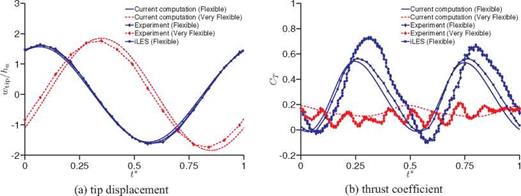
Figure 4.33. Time history of (a) tip displacements and (b) thrust coefficient of a plunging spanwise flexible wing at Re = 3.0 x 10⁴ for different wing stiffness, wing density, and motion frequencies. The experimental data are extracted from Heathcote, Wang, and Gursul [502] and the implicit LES from Gordnier et al. [504]. From Kang et al. [351]. |
Heathcote et al. [502] conducted water-tunnel studies to study the effect of span – wise flexibility on the thrust, lift, and propulsive efficiency of a plunging flexible-wing configuration in forward flight. The leading edge at the wing root was actuated with a prescribed sinusoidal plunge displacement profile. Wing shape was recorded with a 50-frames-per-second, high-shutter-speed, digital video camera. They measured the overall wing thrust coefficient and tip displacement response. Whereas the “inflexible” wing cross-section was built up from nylon and reinforced by steel rods, the “flexible” and “highly flexible” cross-sections were built up from PDMS (rubber) and stiffened with a thin metallic sheet made out of steel and aluminum, respectively (see Fig. 4.28i-iii). Subsequently, computations were conducted on these wing configurations by Chimakurthi et al. [420], Gordnier et al. [504], and Aono et al. [505] at the chord-based Reynolds number of 3×10⁴ using an aeroelastic framework. Recently, Kang et al. [351] examined the effect of spanwise flexibility on the thrust generation for same cases.
In the following discussion we highlight the thrust enhancement mechanism associated with spanwise flexible plunging wings in forward flight for two combinations of density ratios and effective stiffnesses and several motion frequencies at Re = 3.0 x 10⁴ based on the results reported by Kang et al. [351] and Shyy et al. [450]. The vertical displacements of the wingtip from the computations and the experiments for the flexible and very flexible wings are shown in Figure 4.33a. The displacement is normalized with respect to the amplitude of prescribed wing root movement (see Eq. (3-12)). For the flexible wing, in comparison to the tip response presented in previous studies (experiment [502]; implicit LES (iLES) computation [504]), the tip response of the current computation shows good correlation. For the very flexible wing, however, the tip response of the current computation exhibits slight larger amplitude and phase advance compared to the measurements [502].
Time histories of thrust coefficient for the flexible and very flexible wings are shown in Figure 4.33b. For the flexible wing the thrust in the current computation is under-predicted and shows a phase advance compared to the measurements [502]. However, the magnitude and the timing of thrust peaks compare well with
 |
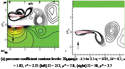
(b) vorticity contour levels: 20; range: -3 to 3
h*s = 0.01, St = 0.1, к = 1.82, t* = 2.25
(left) П = 212, p* = 7.8; (right) П = 38, p* = 2.7
Figure 4.34. Pressure coefficient (p — )/(1pU. r2ef) and vorticity contours at 75 percent span
location for flexible and very flexible wing configurations. The arrow indicates the direction of the airfoil motion. From Kang et al. [351].
the thrust prediction using the iLES [504] coupled with a geometrically non-linear beam solver. Furthermore, the measured thrust is asymmetric in the down – and upstroke, whereas in both computations the thrust has symmetric behavior. For the very flexible wing, the computed thrust history is in a reasonable agreement with the experimental measurements in terms of the amplitude and the trend of thrust. It is worth pointing out that the measurements include higher frequency components, whereas the waveforms of the computed thrust are smooth for all cases [351] [504]. As shown in Figure 4.34, there is no evidence of high-frequency behavior in the tip response. The experimental flow field measurements [502], however, show that the vortex fragments into a collection of weak vortices, and Heathcote et al. [502] suggested that this fragmentation is likely to be responsible for the multiple peaks
 |
observed in the thrust coefficient time histories. Figure 4.34 shows vorticity and pressure contours for the flexible and the very flexible wing configurations at the mid-span section at time instant t* = 0.25, when the wing is at the center of the downstroke. The dominance of leading-edge suction in the flexible case and the reduction of it in the very flexible case are visible in Figure 4.34. The phase lag between the prescribed motion and the deformation of the wing could be used to explain the thrust generation in flexible flapping wings [450]. For the very flexible case the cross-sectional motion is in the opposite direction to the imposed kinematics at the wing root. The phase lags at the wingtip with respect to the prescribed motion for the flexible and very flexible cases are 126°, and -26°, respectively. As a result of the substantial phase lag in the very flexible case, the wingtip and root move in opposite directions during most of the stroke, resulting in lower effective AoAs and consequently lesser aerodynamic force generation; in the contour plots, see also the direction of the arrow denoting the direction of the wing movement.
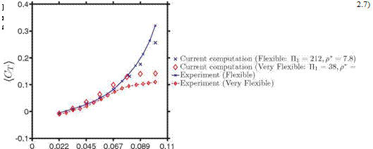
Figure 4.35 shows the time-averaged thrust coefficients for the two different materials for various frequencies of к from 0.4 to 1.82. At higher motion frequencies the time-averaged thrust of the flexible wing is under-predicted by the current computational results, whereas the thrust of the very flexible wing is over-predicted, which again may be ascribed to the uncertainties in the computational modeling or experimental setup. However, the qualitative trend of the thrust response to the variation of the motion frequency is well captured. When the plunging motion is slow (i. e., к < 1.2), the thrust generation is similar for both materials. For higher motion frequencies, the flexible wing benefits more from the flexibility than does the very flexible wing: the thrust saturates for the very flexible wing with increasing St. Furthermore, similar trends are observed: increasing motion frequency enhances thrust, and decreasing the effective stiffness does not necessarily lead to higher thrust.
The structural response is depicted in Figure 4.36. For the flexible wing, the phase lag between the prescribed motion and the tip response for к > 1.4 is from
![Подпись: Ф [deg] Ф [deg] (a) Tip displacement (b) Relative tip deformation Figure 4.36. Tip deformations of a plunging spanwise flexible wing at Re = 3.0 x 10⁴ for different wing stiffness, wing density, and motion frequencies. x П1 = 121, p* = 7.8; ♦П1 = 38, p* = 2.7. From Kang et al. [351].](/img/3131/image444_4.gif)
17.6°-23.8°, whereas for the very flexible wing, Ф varies from 108.8° to 125.9°. The wingtip of the very flexible wing moves in the opposite direction from the root for most of the stroke for higher motion frequencies, whereas for the flexible wing, the wing root and the tip are in phase. This is confirmed in Figure 4.36, where all flexible wing cases show a phase lag of the wingtip relative to the wing root, Ф, less than 90°, and for к = 1.6 and к = 1.82, Ф > 90° for the very flexible wing. Again, the correlations of the dynamics from the root to tip play a key role in the tip displacement, as shown in Figure 4.36, where the relative tip displacement is shown to be monotonic to Ф. The results discussed so far focused on a single Reynolds number 3 x 10⁴. In a parametric study Heathcote et al. [502] found that the mean thrust coefficient is a function of the Strouhal number and is only very weakly dependent on the Reynolds number.


