Our heavyweight helicopter equal in the world does not have
In Rostov started production of the most load-lifting rotary-wing car The Russian holding «Helicopt[...]

Everything about aircrafts and helicopters. News and events in aviation worldwide. Civil, transportation, military helicopters and airplanes.

Everything about aircrafts and helicopters. News and events in aviation worldwide. Civil, transportation, military helicopters and airplanes.

Everything about aircrafts and helicopters. News and events in aviation worldwide. Civil, transportation, military helicopters and airplanes.

Everything about aircrafts and helicopters. News and events in aviation worldwide. Civil, transportation, military helicopters and airplanes.


14.1 THE PROPELLER AS AN ACTUATOR DISC
Early research on propellers, by Rankine and Froude in the 19th century, was concerned with ships’ water screws, but the basic equations of that time remain valid. The propeller was treated as an ‘actuator disc’ which transferred power from the drive shaft to the fluid medium. In the first instance, no attention was paid to the details of the propeller, number of blades and blade shape. The idea was to establish the main principles first, thus opening the way for systematic trials and tests of various propeller forms.
14.2 PROPELLER EFFICIENCY
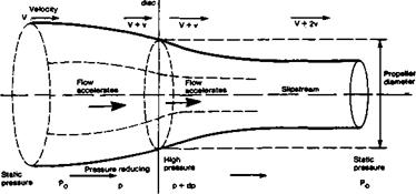
In Figure 14.1 the propeller is represented by a disc of diameter D. It is assumed that the rotation of the blades causes a reduction of pressure over the entire front face of the disc, from Po, the static air pressure at some distance in front of the aeroplane, to p at the disc. The energy transferred to the air by the propeller causes an increase of pressure by some relatively small amount labelled dp (where the small d stands for ‘a relatively small
|
Fig. 14.1 The propeller as an actuator disc 206 |
difference of). The air pressure just behind the disc is then p + dp. Far behind the disc the pressure returns to the static value, Po – The assumption that the pressure change is evenly spread over the whole disc area is false, particularly near the hub of a real propeller, but this obvious simplification and others are taken care of by recognising that no real propeller will be as efficient as the theoretical actuator disc.
Propeller efficiency is defined as the ratio of power supplied to the propeller by the drive shaft, to the useful work or power output i. e.
![]() useful power output _ Thrust x Velocity shaft power input Power
useful power output _ Thrust x Velocity shaft power input Power
The difference in pressure between the front and rear of the disc produces thrust The total thrust can be found very simply by multiplying the difference, dp, by the disc area, which is found from the usual formula for area of a circle. Hence thrust = 0.7854 x D2 x dp, where D is the diameter.
As the diagram shows and as Bernoulli’s theorem leads us to expect (see 2.12), the reduced pressure in front of the disc causes the air to accelerate towards the propeller, V, which corresponds to the airspeed of the aeroplane, thus becoming V + v as the air passes through the disc. Behind the propeller, because of the increased pressure there, the flow accelerates away so the velocity increases further to V + 2v some distance behind. Half the increase of ‘slipstream’ velocity thus occurs ahead of a propeller and half behind it (This is why loose objects such as grass clippings or the end of model flier’s tie flapping loose, may be drawn into the propeller disc.) The slipstream diameter contracts both in front of and behind the propeller, as shown.
The ratio of v to V, the velocity of flight compared with the increment of flow speed through the disc, is of great importance and is termed the ‘inflow factor*, often represented in formulae by a tagged letter a, thus: Inflow Factor = a’ = v/V.
![]()
The Froude or ‘ideal’ efficiency of a propeller is found by relating thrust to flight speed and the inflow factor. The figure resulting is always less than 1.0. The equation is:
The thrust factor cancels out and since v/V = a’, the formula simplifies to:
![]() _J___
_J___
1 + a’
It is now possible to measure the actual thrust, and inflow factor, of any real propeller and compare the figures with the Froude ideal, which determines an absolute limit at a particular airspeed and power input Exceptionally well designed propellers may exceed 90% efficiency at best. A crude propeller, even though looking something like the right shape, may only achieve 50% or so efficiency. It is clear that no model flier can afford to neglect the propeller, since a bad choice may be equivalent to using a motor with forty percent less power output